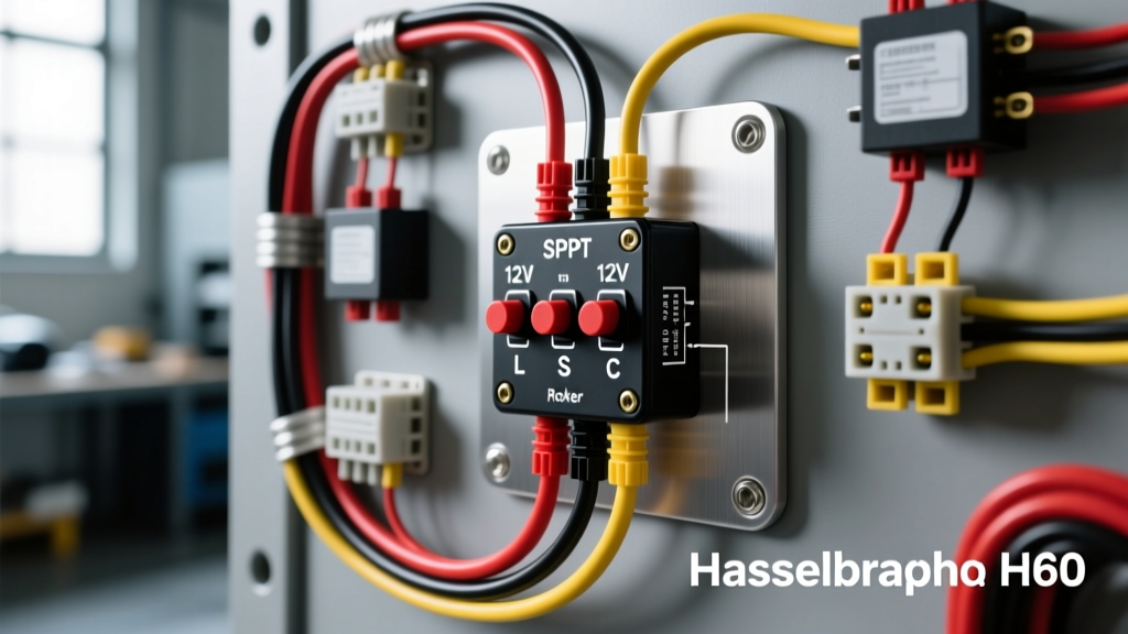
Anatomy of the 3 Prong Rocker Switch (SPST Illuminated)
When integrating auxiliary lighting, winches, or onboard air compressors into a 12V DC automotive electrical system, the three prong rocker switch is the industry standard for Single Pole, Single Throw (SPST) applications. Unlike the 5-pin DPDT (Double Pole, Double Throw) variants used for polarity reversal or dual-circuit isolation, the 3-pin SPST switch features a simplified internal topology designed specifically to handle a single load circuit while providing independent LED illumination feedback.
Understanding the internal routing of a three prong rocker switch is critical before making any terminal crimps. Inside the polycarbonate or nylon housing, you will find a copper-alloy contact bridge and a discrete LED circuit. The LED is wired in parallel to the load circuit but requires its own dedicated ground path to complete the illumination loop. Misidentifying these terminals is the leading cause of melted switch housings, blown inline fuses, and parasitic battery draws in aftermarket off-road builds.
Terminal Identification and Internal Routing
Standard automotive 3-pin rocker switches utilize 0.250-inch (6.35mm) quick-disconnect spade terminals. While manufacturer stampings can vary slightly, the universal pinout configuration for a 12V DC illuminated SPST switch is as follows:
- Pin 1 (Power In / Source): Receives +12V DC from the battery or a fused ignition-switched bus bar. This terminal feeds both the main load contact bridge and the internal LED resistor network.
- Pin 2 (Load Out / Accessory): The switched output. When the rocker actuator is depressed, the internal bridge connects Pin 1 to Pin 2, sending +12V to your accessory or relay coil.
- Pin 3 (LED Ground): Dedicated ground for the internal indicator LED. This must be tied to a clean chassis ground. It does not carry the main load current.
Complete Wiring Diagram Walkthrough: Relay Integration
While a 20A-rated three prong rocker switch can theoretically handle direct loads like small LED pods or 12V cooling fans, best practice in automotive electrical engineering dictates using the switch solely as a low-current trigger for a standard Bosch-style ISO mini relay. This prevents high-current arcing across the switch's internal copper contacts, drastically extending the component's lifecycle and eliminating voltage drop at the dashboard or switch panel.
Circuit Path A: The LED Illumination Loop
The illumination circuit operates independently of the main load bridge but relies on Pin 1 for power. When +12V is present at Pin 1, current flows through the internal current-limiting resistor and the LED diode, exiting at Pin 3.
Routing: Pin 3 (Switch) → 18 AWG Black Wire → Ring Terminal → Chassis Ground.
Expert Note: If Pin 3 is left ungrounded, the switch will still operate the main load, but the LED will remain dark. If Pin 3 is accidentally bridged to Pin 2 (Load Out), the LED will backfeed voltage into the accessory circuit, potentially causing sensitive solid-state relays or ECU modules to behave erratically.
Circuit Path B: The Load and Relay Trigger Loop
This is the primary switching circuit. We will route this to the electromagnetic coil of a 40A automotive relay.
- Source Power: Run 14 AWG red wire from the battery positive terminal to an inline ATO/ATC fuse holder (rated at 15A for 14 AWG wire protection). From the fuse, route the wire to Switch Pin 1.
- Trigger Output: Connect 14 AWG blue wire to Switch Pin 2. Route this to the relay harness Pin 85 (Relay Coil Input).
- Relay Coil Ground: Connect 14 AWG black wire from relay Pin 86 to a verified chassis ground.
- High-Current Load Path: Run 10 AWG red wire from the battery (via a 30A or 40A maxi-fuse) to relay Pin 30 (Common Input). Run 10 AWG red wire from relay Pin 87 (Normally Open Output) to the positive terminal of your accessory (e.g., light bar). Ground the accessory negative terminal directly to the chassis.
For comprehensive wire insulation and stranding specifications, always refer to the SAE J1128 Low Tension Primary Cable standards to ensure your copper wire can withstand under-hood thermal cycling.
Advanced Installation: Inductive Kickback and Flyback Diodes
A frequently overlooked failure mode in three prong rocker switch installations is contact pitting caused by inductive kickback. When the switch is opened (turned off), the electromagnetic field in the relay coil collapses, sending a high-voltage reverse spike back toward Pin 2 of the switch. Over time, this arc degrades the copper contacts, leading to high resistance and eventual thermal meltdown of the plastic switch housing.
To prevent this, wire a 1N4007 flyback diode in parallel with the relay coil. Connect the cathode (striped end) to the +12V trigger wire at Relay Pin 85, and the anode to the ground wire at Relay Pin 86. This creates a safe recirculation loop for the voltage spike, protecting your switch contacts. For more on relay coil suppression, consult the Littelfuse Automotive Relay Application Guidelines.
Pinout, Wire Gauge, and Color Code Specification Chart
| Terminal / Pin | Function | Recommended AWG | Standard Color Code | Termination Type |
|---|---|---|---|---|
| Switch Pin 1 | +12V Source (Fused) | 14 AWG | Red | 0.250' Female Spade |
| Switch Pin 2 | Load / Relay Trigger | 14 AWG | Blue or White | 0.250' Female Spade |
| Switch Pin 3 | LED Ground | 18 AWG | Black | 0.250' Female Spade |
| Relay Pin 30 | High Current +12V In | 10 AWG | Red | Ring Terminal (5/16') |
| Relay Pin 87 | High Current Load Out | 10 AWG | Red | Ring / Butt Splice |
| Relay Pin 85 | Coil Trigger (+) | 14 AWG | Blue | 0.250' Female Spade |
| Relay Pin 86 | Coil Ground (-) | 14 AWG | Black | Ring Terminal |
Step-by-Step Termination and Weatherproofing
The environment beneath a dashboard or inside an engine bay is hostile to exposed copper. Vibration, humidity, and thermal expansion will loosen poorly crimped terminals, increasing resistance and generating heat.
- Strip the Wire: Use a precision wire stripper to remove exactly 5/16' of insulation. Do not nick the outer strands of the stranded copper, as this reduces the wire's tensile strength and ampacity.
- Crimp the Terminal: Use a ratcheting open-barrel or closed-barrel crimp tool specific to 14 AWG non-insulated terminals. A proper crimp will deform the terminal wings into a hexagonal or B-shape, cold-welding the copper strands together.
- Seal the Connection: Slide a piece of 3:1 shrink ratio, adhesive-lined dual-wall heat shrink tubing over the terminal before crimping. After crimping, apply heat evenly until the tubing shrinks and the inner meltable adhesive extrudes slightly from the edges. This creates an IP67-rated waterproof seal that prevents galvanic corrosion and copper oxidation.
Diagnostic Troubleshooting: Multimeter Decision Tree
When a custom accessory fails to power on, avoid the temptation to immediately replace the three prong rocker switch. Use a digital multimeter (DMM) to isolate the fault logically.
Symptom: Accessory Does Not Turn On, Switch LED is OFF
- Check 1: Measure voltage between Switch Pin 1 and Chassis Ground.
Result A (0V): Blown inline fuse or broken power wire from the battery.
Result B (12V): Power is reaching the switch. Proceed to Check 2. - Check 2: Inspect the ground wire on Switch Pin 3. Since the LED is off despite having power at Pin 1, the LED ground circuit is open. Repair the chassis ground connection.
Symptom: Switch LED is ON, but Accessory Does Not Turn On
- Check 1: Turn the switch ON. Measure voltage between Switch Pin 2 and Chassis Ground.
Result A (0V): Internal switch contact bridge has failed. Replace the switch.
Result B (12V): The switch is functioning perfectly. The fault lies downstream. - Check 2: Measure voltage at Relay Pin 85. If 12V is present, check Relay Pin 86 for ground continuity. If the relay coil has power and ground, listen for the mechanical 'click'. If it clicks, test the high-current circuit (Pins 30 and 87) for a blown main fuse or faulty accessory ground.
Symptom: Switch Housing is Hot to the Touch
This is a critical failure state indicating severe voltage drop and high resistance. Immediately disconnect the battery. This is almost always caused by using undersized wire (e.g., 18 AWG on a 15A load without a relay), a loose spade terminal that is arcing, or a failing internal contact bridge. Cut away the damaged terminals, inspect the wire for heat-induced insulation brittleness, and rebuild the circuit using the relay integration method detailed above.