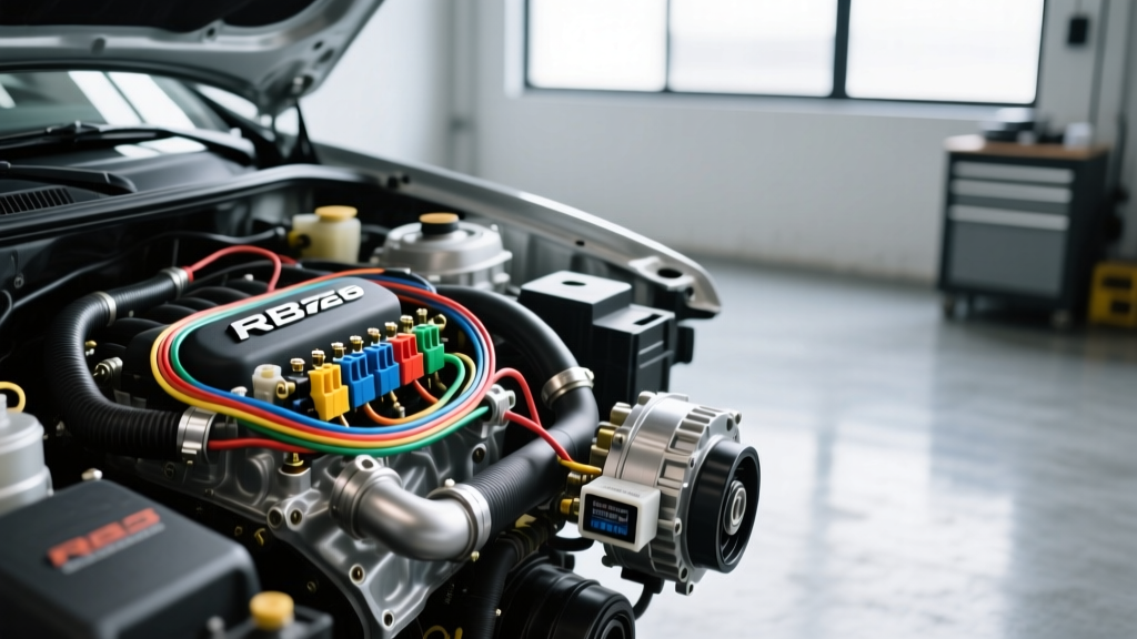
Introduction to RB Auto Electric Modification Projects
The Nissan RB engine series—spanning the RB20DET, RB25DET, and the legendary RB26DETT—remains a cornerstone of the global tuning community. However, executing a flawless engine swap requires far more than mechanical fabrication; the true battleground is the electrical system. The term "RB auto electric" encompasses the complex integration of the Nissan ECCS (Electronic Concentrated Control System) into non-native chassis like the Nissan S13/S14, Toyota JZX100, or custom tube-frame builds. Whether you are merging a donor harness, upgrading the charging system, or extending critical sensor networks, understanding the specific wire colors, AWG requirements, and pin configurations is mandatory for reliability. This guide provides actionable, expert-level wiring protocols for your RB upgrade and modification project.
Core ECCS Harness Merging and ECU Pinouts
When performing an RB swap, the factory engine harness must interface with the chassis bulkhead connector. In many cross-chassis builds, tuners opt to depin the massive Nissan multi-pin bulkhead and hardwire the essential circuits directly into a custom fuse block or the recipient chassis's ECU harness. Soldering and adhesive-lined heat shrink (such as Raychem SCL) are mandatory; crimp-only connectors will eventually fail under engine bay vibration and thermal cycling.
Below is a critical reference table for the R33 RB25DET and R33 RB26DETT ECCS ECU power, ground, and control pins. Always verify against your specific chassis Nissan Factory Service Manual (FSM), as pinouts vary slightly between R32, R33, and R34 generations.
| ECU Pin | Function | Factory Wire Color | Upgrade / Swap Notes |
|---|---|---|---|
| 35 | Ignition Power (Switched 12V) | Black/Yellow | Must be triggered by a clean ignition source. Do not share with high-draw accessories. |
| 105 | Constant Battery Power (Memory) | Red/Blue | Provides ECU memory and constant 12V to the main relay coil. |
| 104, 106 | Main ECU Ground | Black | Ground directly to the cylinder head or a dedicated chassis ground bus. Use 12 AWG minimum. |
| 114 | Fuel Pump Relay Control | Green/White | Ground-side trigger. The ECU provides the ground path to activate the fuel pump relay. |
| 110 | Main Relay Control | Yellow/Blue | Ground-side trigger for the ECCS main relay, which feeds power to the injectors and coils. |
Upgrading the Alternator and Starter Circuits
Stock RB26DETT alternators typically output between 80A and 90A. In modern RB auto electric builds featuring high-flow fuel pumps (e.g., dual Walbro 450s or E85 setups), electric cooling fans, and aftermarket ignition systems, 80A is insufficient. Upgrading to a 150A+ Denso or custom aftermarket alternator requires a complete overhaul of the charging circuit.
The 3-Pin Alternator Connector Protocol
Nissan alternators utilize a specific 3-pin regulator plug. Miswiring this plug is the leading cause of overcharging and boiled batteries in RB swaps.
- IG (Ignition): Switched 12V. This wakes the internal voltage regulator. Connect to an ignition-switched fuse.
- L (Lamp): Provides a ground path for the dashboard charge indicator light. If your swap chassis lacks this bulb, wire a 12V test light or a 470-ohm resistor to ground to satisfy the regulator's initial excitation circuit.
- S (Sense): Critical Upgrade Point. This wire measures actual battery voltage. The factory harness often routes this to the alternator B+ terminal or a nearby junction. In a modified build with heavy electrical loads, voltage drop across the harness will trick the regulator into overcharging (pushing 15.5V+). You must run a dedicated 16 AWG or 14 AWG sense wire directly from the alternator plug to the battery positive terminal or the main distribution block.
Main Charge Wire: Upgrade the alternator B+ charge wire from the factory 8 AWG to 4 AWG or 2 AWG OFC (Oxygen-Free Copper) to handle 150A+ safely without thermal degradation. Follow SAE J1128 Low Tension Cable Standards for under-hood temperature ratings.
Sensor Extensions: CAS, MAF, and EMI Shielding
The Crank Angle Sensor (CAS) is the Achilles heel of RB auto electric projects. Located inside the cam housing (on R32/R33 engines), the optical CAS outputs a 12V square wave signal (1° and 180° timing marks). This high-voltage digital signal is highly susceptible to Electromagnetic Interference (EMI), especially if you have upgraded to R35 coil packs, LS coils, or high-output ignition systems.
Shielding the CAS and MAF Harness
When extending the CAS or Mass Air Flow (MAF) sensor harness to accommodate a custom intake plenum or engine set-back, you must use shielded cable. Standard unshielded primary wire will act as an antenna, absorbing ignition noise and causing erratic timing scatter or phantom misfires at high RPM.
- Wire Selection: Use a 3-conductor or 4-conductor shielded cable (e.g., Belden 8760 or equivalent automotive-grade shielded wire, 18 AWG to 20 AWG for signal wires).
- Drain Wire Grounding: The shield contains a bare copper "drain wire." This drain wire must be grounded at the ECU connector end ONLY. Grounding the shield at both the sensor and the ECU creates a ground loop, which will induce 60Hz+ alternator whine and noise directly into the ECU's logic board.
- MAF Sensor: The RB MAF requires a clean 5V reference, a dedicated sensor ground, and the signal return. Keep MAF wiring at least 4 inches away from ignition coil power wires and fuel injector harnesses.
Grounding Strategy and Chassis Prep
An RB engine block sitting on rubber motor mounts is electrically isolated from the chassis. Relying on the starter motor ground or thin sensor grounds to carry return current will result in voltage drops across the ECU sensors, causing the ECU to read inaccurate TPS and coolant temperatures.
- Engine to Chassis: Use 1/0 AWG welding cable with heavy-duty copper lugs. Crimp using a hex-style hydraulic crimper.
- Surface Prep: Remove all paint, powder coat, and rust from the chassis grounding point and the engine block mounting boss. Use a wire wheel or sanding disc down to bare, shiny metal.
- Corrosion Protection: After torquing the ground strap (typically M10 or M12 hardware, torqued to 25-35 lb-ft depending on the stud), coat the entire terminal and exposed bare metal in dielectric grease or a dedicated copper anti-seize compound to prevent galvanic corrosion.
Troubleshooting Common RB Electrical Gremlins
Even with meticulous planning, RB swaps can present unique electrical faults. Use this decision tree to diagnose common issues:
- Symptom: Crank, No Spark / No Injector Pulse.
Cause: CAS signal loss or ECCS Main Relay failure.
Fix: Verify 12V at the CAS power wire during crank. Check the ECU Pin 110 ground trigger for the main relay. Ensure the CAS rotor is physically installed and not slipping on the camshaft dowel. - Symptom: Engine Starts but Idles Erratically / Stalls.
Cause: TPS (Throttle Position Sensor) voltage mismatch or AAC (Auxiliary Air Control) valve wiring reversal.
Fix: Backprobe the TPS. Pin 2 should read exactly 0.50V at idle (closed throttle). If using an adapter harness, verify the AAC valve solenoid pins are not crossed, as this will cause the idle air bypass to fully close or fully open unexpectedly. - Symptom: Battery Overcharging (15.0V+ at idle).
Cause: Alternator Sense (S) wire voltage drop.
Fix: Reroute the 16 AWG Sense wire directly to the battery positive terminal. Do not rely on the alternator B+ post for voltage sensing in high-amp setups.
Authoritative References
For deeper wiring diagrams, pinout matrices, and factory torque specifications, always consult the primary engineering documentation. The following resources are essential for any RB auto electric build:
- Nissan Factory Service Manuals (NicoClub Archive) - Comprehensive ECCS wiring diagrams for R32, R33, and R34 chassis.
- SAE J1128 Low Tension Cable Standards - Specifications for automotive wire gauge, insulation temperature ratings, and current capacity.
- GTR Registry RB Engine Archives - Community-verified data on RB26DETT harness variations and alternator upgrade part numbers.