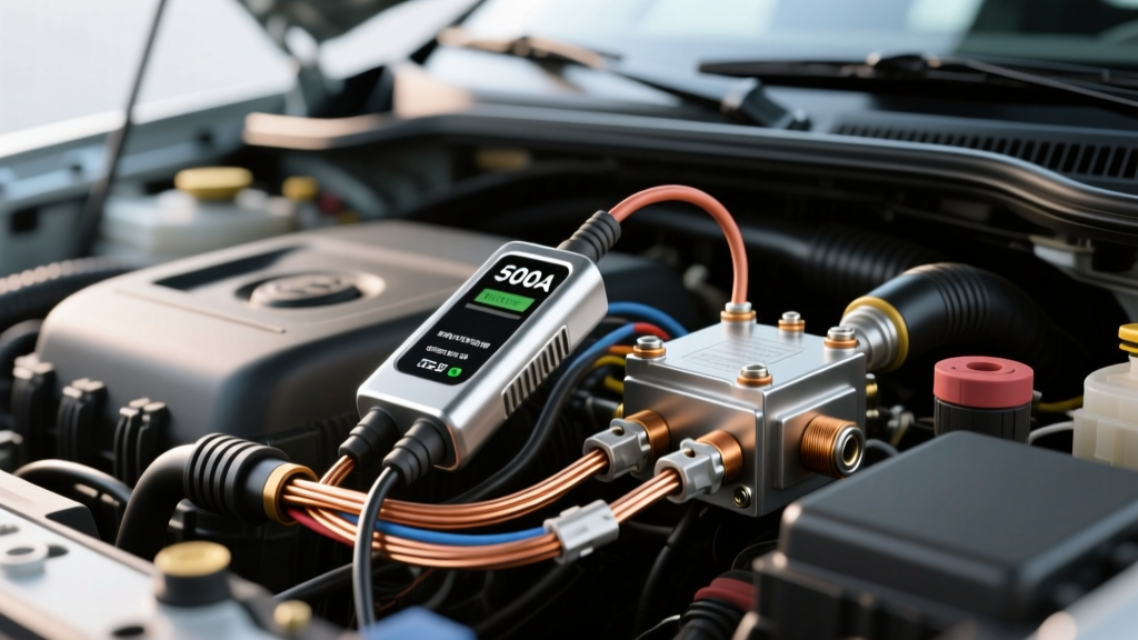
Why Install a Permanent Auto Electrical Tester System?
When diagnosing complex parasitic draws or verifying high-output alternator performance, relying solely on a handheld multimeter is often insufficient. A permanent inline auto electrical tester system—centered around a high-amperage current shunt and a digital monitoring display—provides real-time, continuous data on your vehicle's electrical architecture. This setup is critical for overland builds, heavy-duty diesel trucks, and off-road vehicles where auxiliary loads (winches, lighting, compressors) frequently push the charging system to its limits.
By installing a 500A/50mV shunt on the main ground bus and integrating a fused diagnostic breakout port, you create a centralized hub for testing. This allows you to connect portable diagnostic tools safely without piercing wire insulation or risking a short circuit. According to SAE J1128 standards for low-tension primary cable, maintaining signal integrity and minimizing voltage drop is paramount when routing high-current and low-voltage signal wires in the same engine bay.
Component Specifications and Bill of Materials
Before beginning the installation, ensure you have the correct automotive-grade components. Using undersized wire or non-sealed connectors will lead to galvanic corrosion and inaccurate tester readings.
| Component | Specification | Purpose |
|---|---|---|
| Current Shunt | 500A / 50mV Continuous | Measures total system DC current flow |
| Main Battery Cable | 2/0 AWG OFC (Oxygen-Free Copper) | Primary ground path from battery to chassis/engine |
| Signal Wire | 18 AWG Twisted Pair (Shielded) | Transmits millivolt signal to the digital monitor |
| Diagnostic Connector | Deutsch DT 4-Pin Receptacle | Sealed breakout port for external auto electrical tester |
| Heat Shrink | 3mm & 12mm Dual-Wall (Adhesive-Lined) | Waterproofing and strain relief for crimps |
| Terminal Torque | 10 Nm (88 in-lbs) | Shunt terminal nut specification |
Phase 1: Mounting the 500A Current Shunt
The most accurate way to measure total vehicle electrical load and parasitic draw is to install the shunt on the negative (ground) side of the battery. This keeps the high-current B+ positive cables untouched, reducing the risk of catastrophic short circuits during installation.
- Isolate the System: Disconnect the negative battery terminal first, followed by the positive. Wait 15 minutes for vehicle modules to enter sleep mode.
- Mount the Shunt: Locate a flat, clean surface on the chassis or battery box near the negative battery post. Bolt the shunt base down using stainless steel hardware. Ensure the shunt is oriented so that the 'Battery' side faces the negative post, and the 'System/Load' side faces the chassis ground bus.
- Prepare the 2/0 AWG Cable: Cut a length of 2/0 AWG black OFC wire to bridge the battery negative post to the 'Battery' side of the shunt. Strip exactly 7/8 inch of insulation. Do not nick the copper strands.
- Hex Crimp and Seal: Insert the wire into a 2/0 AWG closed-end copper lug. Use a 6-ton hydraulic or ratcheting hex crimper. Slide a piece of 12mm dual-wall adhesive heat shrink over the crimp barrel and apply heat until the adhesive purges from the edges.
- Torque the Terminals: Secure the 2/0 AWG lugs to the shunt terminals using the provided brass nuts. Torque to exactly 10 Nm (88 in-lbs). Over-torquing can strip the brass threads, while under-torquing creates a high-resistance joint that will melt under heavy alternator charging loads.
- Reconnect the Main Ground: Attach the original vehicle chassis ground cable to the 'System/Load' side of the shunt. If multiple ground cables exist, combine them using a heavy-duty copper busbar before routing to the shunt.
Phase 2: Routing Signal Wires and EMI Protection
The auto electrical tester monitor relies on reading a tiny 0-50 millivolt signal across the shunt. Alternator whine and electromagnetic interference (EMI) from ignition coils can easily corrupt this signal, causing erratic amperage readings on your display.
Twisted Pair Routing Protocol
- Wire Colors: Use Yellow for Signal+ and White for Signal-. Use 18 AWG stranded copper.
- Twisting: Twist the Yellow and White wires together at a rate of at least 4 twists per inch. This common-mode rejection technique cancels out external EMI.
- Clearance: Route the twisted pair at least 6 inches away from the alternator output B+ wire, ignition coil packs, and starter solenoid trigger wires. If crossing a high-voltage wire is unavoidable, cross it at a strict 90-degree angle.
- Shielding: For vehicles with high-output audio amplifiers or aftermarket ignition systems, wrap the twisted pair in a tinned copper braided sleeve and ground the sleeve at the monitor end only (pigtail ground) to prevent ground loops.
Phase 3: Wiring the Diagnostic Breakout Test Port
To make your permanent auto electrical tester setup truly versatile, we will install a sealed diagnostic breakout port. This allows you to plug a portable Power Probe or secondary multimeter directly into the main battery bus safely, bypassing the need to reach the physical battery terminals.
- Select the Connector: Use a 4-pin Deutsch DT receptacle (Part # DT04-4P). This provides two heavy-duty pins for power and two for CAN/Signal if needed in the future.
- Wire the Power Pins: Run a 10 AWG red wire from the main B+ battery post through a 30A MAXI fuse holder, terminating at Pin 1 of the Deutsch connector. Run a 10 AWG black wire from the chassis ground bus to Pin 2.
- Crimp and Seal: Use Deutsch-specific solid core pins. Crimp the 10 AWG wire using a precision indent crimper. Insert the pins into the housing until you hear the audible click. Insert the orange wedge lock to prevent the pins from backing out under vibration.
- Mounting: Mount the receptacle in the engine bay or cab firewall using a stainless steel bracket. Apply a dab of dielectric grease to the mating plug to prevent moisture ingress and oxidation.
As noted in the Blue Sea Systems Shunt Installation Guide, keeping diagnostic taps fused and properly sealed is essential for preventing localized electrical fires in harsh environments.
Calibration and Real-World Troubleshooting
Once the physical installation is complete, reconnect the battery and power up the digital monitor. You must calibrate the system to account for wire resistance and baseline parasitic draw. For deeper alternator ripple testing, refer to Haynes Alternator Testing procedures using an oscilloscope on your newly installed breakout port.
Symptom-Cause-Fix Decision Tree
| Symptom on Tester Display | Probable Cause | Corrective Action |
|---|---|---|
| Monitor reads -15A to -40A with engine OFF and keys out. | Massive parasitic draw or modules failing to sleep. | Pull fuses one by one. If draw persists, check for aftermarket alarms or amplifiers wired upstream of the shunt. |
| Amperage reading fluctuates wildly (e.g., +50A to -50A) at idle. | EMI interference on the 18 AWG signal wires. | Verify twisted pair routing. Ensure signal wires are not zip-tied to the alternator B+ cable. |
| Monitor reads 0A while cranking the starter motor. | Shunt installed backward or signal wires swapped. | Swap the Yellow (Signal+) and White (Signal-) wires at the monitor terminal block. |
| Display shows correct amps, but voltage reads 2V lower than actual battery. | High resistance on the monitor's voltage sense wire. | Check the inline fuse on the red B+ sense wire and clean the ring terminal connection at the battery post. |
Final Verification
Start the engine and turn on all major electrical loads (headlights, HVAC blower on high, rear defroster). The auto electrical tester should display a positive amperage reading indicating the alternator is supplying the system and charging the battery. Turn the engine off; the display should drop to a negative reading representing the vehicle's baseline parasitic draw (typically -30mA to -80mA for modern CAN-bus vehicles). By installing this permanent inline testing architecture, you eliminate guesswork and establish a reliable baseline for all future automotive electrical diagnostics.