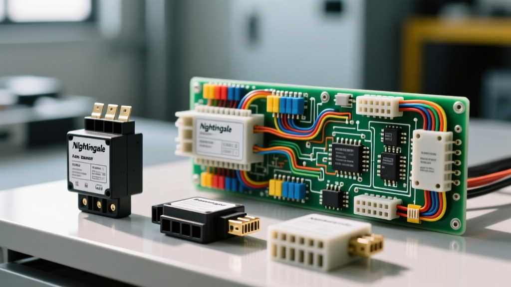
Introduction to Nightingale Auto Electric Architectures
When building a robust dual-battery system or wiring a heavy-duty towing rig, selecting the right control components is critical to prevent parasitic drain and protect sensitive vehicle electronics. Nightingale auto electric components have become a staple in the 4x4, RV, and commercial towing sectors due to their heavy-duty encapsulation, high current tolerances, and smart sensing capabilities. Unlike generic automotive relays that often fail under continuous high-amperage loads or extreme under-hood temperatures, Nightingale's engineered solutions are designed specifically for the harsh realities of auxiliary power management and trailer lighting integration.
This comprehensive selection guide compares Nightingale smart isolators, standard continuous-duty solenoids, and bypass modules, providing exact wiring specifications, AWG sizing, and pinout configurations required for a safe, compliant, and reliable installation. Whether you are upgrading a fleet of commercial tow vehicles or outfitting an overland expedition truck, understanding the architecture of these components is the first step toward a failure-free electrical system.
Component Selection: Smart Isolators vs. Solenoids vs. DC-DC Chargers
Choosing the correct battery management device depends entirely on your alternator type (smart vs. fixed output), cable run distance, and auxiliary battery chemistry. Below is a technical comparison of the primary Nightingale auto electric battery isolation methods versus traditional alternatives.
| Feature | Nightingale SBI (Smart Battery Isolator) | Standard Continuous Solenoid | DC-DC Battery Charger |
|---|---|---|---|
| Primary Function | Automatic voltage-sensing parallel connection | Manual or ignition-switched parallel connection | Multi-stage charging & voltage regulation |
| Current Rating | Typically 140A to 200A continuous | 150A to 250A (high heat generation) | 20A to 60A (limited by internal electronics) |
| Smart Alternator Compatible? | No (Requires fixed voltage >13.2V to engage) | No (Will disconnect during Eco-Stop/Decel) | Yes (Specific models feature ignition sense / D+ trigger) |
| Parasitic Draw | < 2mA (Ultra-low standby) | High (Coil requires constant current to hold) | Low (< 5mA standby) |
| Ideal Application | Older vehicles, winching, auxiliary cranking | Heavy-duty commercial PTO, manual winch control | Modern CAN-bus vehicles, Lithium (LiFePO4) aux batteries |
Wiring the Nightingale 140A Smart Battery Isolator (SBI)
The Nightingale SBI monitors the voltage of both the primary (cranking) and secondary (auxiliary) batteries. It engages an internal latching relay only when it detects a charging voltage (typically >13.2V) on either side, and disconnects when voltage drops below 12.7V to protect the cranking battery from deep discharge. Because it handles the full output of the alternator during bulk charging, the wiring must be sized to handle high amperage without excessive voltage drop.
Cable Sizing and Termination Specifications
- Main Power Cables: Use 4 AWG (21.15 mm²) stranded copper wire for cable runs up to 3 meters. For runs exceeding 3 meters (common in RVs where the aux battery is in the rear), upgrade to 2 AWG (33.62 mm²) to maintain a voltage drop below 0.2V at 100A.
- Terminals: Use heavy-duty copper tube lugs with a 10mm hex crimp die. Do not use solder-only connections; the heat from a 140A load will melt solder. Crimp using a hydraulic or heavy ratcheting tool, then seal with dual-wall heat shrink containing polyamide adhesive.
- Torque Specifications: The M8 terminal nuts on the Nightingale SBI posts must be torqued to exactly 10-12 Nm (7.4-8.8 lb-ft). Over-torquing will strip the brass threads; under-torquing will create a high-resistance joint leading to thermal runaway.
- Sense and Ground Wires: The small sense wires should be 16 AWG. Route these at least 4 inches away from the main alternator output cables to prevent inductive interference, which can cause the SBI to chatter or falsely engage.
Step-by-Step Installation Sequence
- Disconnect the negative terminal on the primary cranking battery to eliminate short-circuit risks.
- Mount the Nightingale SBI in a location protected from direct water ingress and extreme exhaust heat (IP67 rated, but thermal management is still required for the internal coil).
- Run the 4 AWG cable from the primary battery positive to the 'Start' terminal on the SBI, integrating a 150A ANL fuse within 150mm of the battery post.
- Run the secondary 4 AWG cable from the 'Aux' terminal to the auxiliary battery positive, integrating a second 150A ANL fuse near the auxiliary battery.
- Connect the 16 AWG ground wire to a clean, unpainted chassis ground point. Use a star washer to bite through the paint and apply dielectric grease to prevent corrosion.
- Reconnect the primary battery and verify operation using a multimeter. With the engine off, both sides should read ~12.6V and show infinite resistance between posts. Start the engine; once alternator voltage exceeds 13.2V, you should hear a distinct click, and both posts should read identical charging voltage (13.8V - 14.4V).
CAN-Bus Trailer Modules and Bypass Relays
Modern vehicles utilize Multiplex wiring and Body Control Modules (BCMs) that monitor trailer lighting circuits via Pulse Width Modulation (PWM). If you wire a standard trailer directly into a modern vehicle's tail light harness, the low current draw of LED trailer lights will trick the BCM into thinking a bulb has blown, triggering dash warnings or cutting power to the circuit entirely. Nightingale auto electric bypass modules solve this by drawing power directly from the battery and using the vehicle's lighting circuits only as high-impedance signal triggers.
12-Pin Flat Connector Pinout (AS 4735 Standard)
When integrating a Nightingale bypass module with a 12-pin flat trailer plug (common in Australian and heavy-duty RV markets per AS 4735 standards), precise pin mapping is essential to prevent cross-circuit shorts and reverse-polarity damage to the module's internal MOSFETs.
| Pin | Wire Color | Function | Module Connection Note |
|---|---|---|---|
| 1 | Yellow | Left Turn Signal | Connect to Bypass Module 'Left Trigger' |
| 2 | Black | Earth (Ground) | Heavy chassis ground, 10 AWG minimum |
| 3 | Red | Stop Lights | Connect to Bypass Module 'Stop Trigger' |
| 4 | Green | Right Turn Signal | Connect to Bypass Module 'Right Trigger' |
| 5 | Brown | Tail / Clearance Lights | Connect to Bypass Module 'Tail Trigger' |
| 6 | Blue | Electric Brakes | Direct from Brake Controller (Bypass Module N/A) |
| 7 | Black | Earth (Ground) | Secondary ground for redundancy |
| 8 | Pink | Reverse Lights | Trigger for reverse camera / solenoid lockout |
| 9 | Orange | Rear Fog | Often unused in North American markets |
| 10 | White | Ignition / 12V Switched | Trigger for auxiliary fridge relays |
| 11 | White | Auxiliary / 12V Switched | Backup circuit for PTO or work lights |
| 12 | Red | Constant 12V (Battery) | Direct from battery via 30A auto-reset breaker |
Advanced Troubleshooting: Voltage Drop & PWM Errors
Even with premium Nightingale auto electric components, environmental factors and poor termination can lead to system faults. Use the following diagnostic decision tree to isolate issues in dual-battery and towing setups.
Symptom: Auxiliary Battery Not Charging / SBI Not Engaging
- Test Alternator Output: Measure voltage at the primary battery posts with the engine at 2000 RPM. If voltage is below 13.2V (common with smart alternators in Eco mode), the SBI will not engage. Fix: Install a D+ ignition trigger wire to force the SBI to engage, or switch to a DC-DC charger.
- Perform Voltage Drop Test: Place multimeter probes across the main ANL fuse and the SBI terminal. A reading greater than 0.1V indicates a corroded lug or loose crimp. Fix: Cut, strip, and re-crimp the terminal.
- Check Sense Wire Ground: If the SBI ground wire shares a stud with a high-current inverter, ground bounce can confuse the internal logic board. Fix: Run a dedicated 16 AWG ground directly to the negative battery post.
Symptom: Trailer Brake Controller Shows 'Overload' or 'Short Circuit'
This is rarely a failure of the Nightingale module itself, but rather a failure in the 7-pin or 12-pin trailer plug. According to SAE J560 and related heavy-duty connector standards, the blue electric brake wire (Pin 2 on 7-way, Pin 6 on 12-way) is highly susceptible to moisture ingress.
- Diagnostic Step: Disconnect the trailer plug at the vehicle bumper. Measure resistance between the Blue (Brake) pin and the White/Black (Ground) pin on the trailer side.
- Expected Reading: 3.0 to 5.0 Ohms (depending on the number of brake magnets).
- Failure Reading: 0.0 Ohms (Dead short in trailer wiring harness) or Infinite/OL (Broken wire or corroded magnet coil).
- Module Protection: Nightingale bypass modules feature internal thermal cutoffs. If a short in the trailer lighting circuit overheats the module, it will shut down. Allow 10 minutes for cool-down, fix the trailer short, and the module will automatically reset.
Conclusion
Integrating Nightingale auto electric components into your vehicle's architecture requires strict adherence to AWG sizing, proper torque specifications, and an understanding of modern CAN-bus monitoring systems. By selecting the correct Smart Battery Isolator for your alternator type and utilizing PWM-compatible bypass relays for trailer lighting, you ensure a resilient electrical system capable of handling the extreme demands of towing and off-grid exploration. Always verify your pinouts against regional standards, utilize marine-grade tinned copper for all exterior connections, and protect every high-amperage circuit with appropriately rated ANL or Mega fuses.