Why Foundational Knowledge Matters Before Your Online Auto Electrical Course
Enrolling in an online auto electrical course is one of the smartest investments a DIY mechanic or aspiring technician can make. Modern vehicles are essentially rolling networks of CAN-bus modules, pulse-width modulated sensors, and high-amperage charging systems. However, before you can diagnose a parasitic draw on a 2018 Ford F-150 or trace a LIN-bus communication fault, you must master the physical layer of automotive wiring. Many students jump straight into complex oscilloscope diagnostics without understanding the baseline behavior of copper, insulation ratings, and electromagnetic switching. This guide serves as your pre-course primer, detailing the exact SAE standards, wire gauges, and component architectures you will encounter in your curriculum.
Decoding the SAE J1128 Standard and Automotive Wire Colors
Unlike household wiring, which relies on a simple Black/White/Green color palette, automotive harnesses utilize a complex color-coding system governed by the SAE International J1128 standard. This standard dictates not only the color abbreviations but also the insulation thickness, temperature resistance (typically rated for 125°C), and chemical resistance to under-hood fluids.
Standard SAE Color Abbreviations
When reading a factory wiring diagram from Haynes, Chilton, or an OEM service manual, you will rarely see full color names. Instead, you will see two-letter abbreviations. Memorizing these is your first step in any online auto electrical course:
- BK: Black (Usually primary ground)
- RD: Red (Usually primary battery power, B+)
- GN: Green
- GY: Gray
- WT: White
- VT: Violet / Purple
- BN: Brown
- OG: Orange
- YE: Yellow
- LB: Light Blue
- DB: Dark Blue
- DG: Dark Green
- PK: Pink
- TN: Tan
Expert Note: Tracer colors are often denoted with a slash. For example, 'RD/WT' indicates a Red wire with a White stripe. In high-current circuits, the base color indicates the primary function, while the tracer denotes the specific circuit branch.
AWG vs. Metric: Sizing and Current Capacity
North American vehicles primarily use the American Wire Gauge (AWG) system, while European and Asian manufacturers often specify cross-sectional area in square millimeters (mm²). A critical concept taught in foundational electrical modules is that wire size is dictated by current (Amperes) and length, not voltage. A 12V system requires thicker insulation than a 5V logic circuit, but the copper diameter is strictly a function of amperage and voltage drop limits.
| AWG Size | Metric Equiv (mm²) | Max Continuous Amps (SAE) | Common Automotive Application |
|---|---|---|---|
| 1/0 AWG | 50.0 mm² | 150A - 200A | Alternator to Battery B+, Starter Motor Feed |
| 4 AWG | 20.0 mm² | 60A - 80A | High-Output Audio Amplifiers, Winch Power |
| 10 AWG | 5.0 mm² | 30A | Electric Cooling Fans, Power Windows, ABS Pumps |
| 14 AWG | 2.0 mm² | 15A | Headlights, Fuel Pumps, Cigar Lighter Sockets |
| 18 AWG | 0.75 mm² | 7A - 10A | ECU Sensor Signals, Tail Lights, Relay Coils |
| 22 AWG | 0.35 mm² | 3A - 5A | CAN-Bus Networking, Low-Current Logic Triggers |
According to AutoShop101 Electrical Fundamentals, exceeding the amperage rating of a specific AWG wire will cause the PVC or cross-linked polyethylene (XLPE) insulation to melt, leading to dead shorts and potential harness fires. Always calculate voltage drop when running wires longer than 10 feet; a 14 AWG wire running 20 feet to a 10A off-road light bar will suffer significant voltage drop, resulting in dim lights and overheated copper.
The ISO Mini Relay: The Heart of Auto Wiring
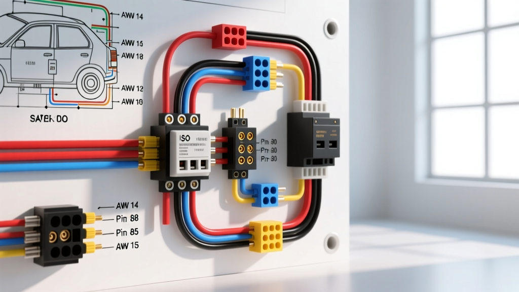
Relays allow a low-current switch (like a dashboard button or an ECU transistor) to control a high-current load (like a starter solenoid or cooling fan). The most ubiquitous component you will study in your online auto electrical course is the Bosch-standard ISO 7588 Mini Relay. Understanding its internal architecture is non-negotiable for any auto electrician.
Standard 5-Pin ISO Relay Pinout
- Pin 30 (Common / Power Input): Receives direct fused battery voltage (B+). Usually connected via a heavy-gauge wire (12 or 10 AWG).
- Pin 87 (Normally Open - NO): The output to the load. When the relay energizes, the internal contactor bridges Pin 30 to Pin 87.
- Pin 87a (Normally Closed - NC): Connected to Pin 30 when the relay is off. Disconnected when energized. Often used for alarm systems or dual-speed fan setups.
- Pin 85 (Coil Ground): One side of the internal electromagnetic coil. Usually tied to chassis ground or switched by the ECU's low-side driver.
- Pin 86 (Coil Power): The trigger side of the coil. Receives 12V from the ignition switch or control module.
Troubleshooting Insight: As detailed by Bosch Mobility Solutions, relays fail in two primary modes: coil burnout (resulting in no click and infinite resistance across 85/86) and contactor pitting (resulting in high resistance across 30/87, causing voltage drop and melted relay sockets). Always test the load side with a multimeter under actual load conditions, not just with a simple continuity beep test.
Voltage Drop Testing: The Ultimate Diagnostic Skill
If there is one practical skill that separates novices from professionals, it is voltage drop testing. A standard ohmmeter cannot accurately detect high-resistance faults in live circuits because it uses very low test current. Voltage drop testing uses the circuit's own operating current to reveal hidden resistance.
Step-by-Step Voltage Drop Procedure
- Step 1: Set your digital multimeter (DMM) to DC Volts.
- Step 2: Ensure the circuit is powered ON and the load is actively drawing current (e.g., headlights turned on, cooling fan spinning).
- Step 3: Place the DMM's Red probe on the positive battery post and the Black probe on the load's positive terminal. The meter will display the voltage 'lost' pushing current through the positive side of the harness.
- Step 4: Repeat for the ground side: Red probe on the load's negative terminal, Black probe on the negative battery post.
Acceptable Limits: A healthy high-current circuit (like a starter) should show a total voltage drop of less than 0.5V across the entire harness. A low-current sensor circuit should show less than 0.1V. If your meter reads 2.4V on the ground side of a fuel pump circuit, you have found a corroded ground strap or a loose terminal, even if a visual inspection shows no obvious damage.
Connectors and Crimping: Delphi Weather-Pack vs. Metri-Pack
Finally, no foundational course is complete without understanding terminal crimping. Soldering is generally frowned upon in modern automotive harnesses due to the rigid joint it creates, which can snap under engine bay vibration. Instead, manufacturers use mechanical crimps.
The Delphi Weather-Pack connector is the industry standard for aftermarket and heavy-duty sealed connections. Recognizable by its robust nylon housings and silicone rubber seals, it handles up to 20 amps per cavity. The critical failure mode for beginners is using the wrong crimp die. Weather-Pack terminals require a specific dual-crimp die that folds the wire wings around the bare copper and the insulation wings around the wire jacket. Using a generic electrical crimp tool will result in a terminal that pulls out under tension or allows moisture to wick into the harness via capillary action, leading to green copper corrosion (copper oxide) inside the connector body.
Conclusion
Mastering these physical layer fundamentals—SAE color codes, AWG current limits, ISO relay logic, and precise voltage drop testing—will give you a massive advantage when you begin your online auto electrical course. Instead of struggling to understand basic circuit behavior, you will be free to focus on advanced module programming, CAN-bus topology, and oscilloscope waveform analysis. Keep your multimeter handy, respect the SAE standards, and always verify your connections under load.