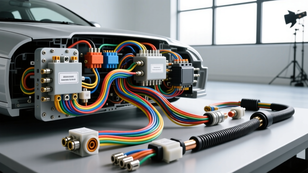
Introduction: The Hidden Cost of Electrical Guesswork
Modern vehicles are essentially rolling networks, relying on complex multiplexed communication and high-amperage power distribution. When DIY enthusiasts or general mechanics attempt electrical modifications without adhering to strict OEM and SAE standards, the results range from intermittent parasitic draws to catastrophic electrical fires. Based on thousands of diagnostic hours and warranty-return teardowns, the master technicians at Sam's Auto Electric and Car Repair have cataloged the most frequent, damaging wiring errors seen in the bay. This guide breaks down these critical mistakes, providing the exact technical specifications, wire gauges, and repair protocols required to maintain vehicle electrical integrity and safety.
Mistake #1: Undersizing Starter and Alternator B+ Cables
One of the most dangerous errors observed at Sam's Auto Electric and Car Repair is the use of undersized battery positive (B+) cables during alternator upgrades or engine swaps. Many assume that if an 8 AWG wire worked for a 100-amp stock alternator, it will suffice for a 200-amp high-output unit. This violates basic electrical physics and SAE J1128 standards for low-tension primary cables.
The Technical Reality: Voltage Drop and Thermal Runaway
When an alternator outputs 180 amps, pushing that current through an 8 AWG copper wire over a 3-foot run creates severe resistance. This resistance manifests as voltage drop and extreme heat. A voltage drop exceeding 0.2V across the B+ cable forces the alternator's internal voltage regulator to overcompensate, leading to premature diode bridge failure and melted insulation. Furthermore, starter circuits draw 250 to 400 amps momentarily; undersized cables here cause solenoid chatter and severe cranking voltage drop.
Specification Chart: B+ Cable Sizing (Copper, 12V Systems)
| Max Continuous Amperage | Minimum AWG Size (Under Hood) | Recommended AWG (High Temp) | Max Allowable Voltage Drop |
|---|---|---|---|
| 80A - 120A | 6 AWG | 4 AWG | 0.2V |
| 130A - 180A | 2 AWG | 1 AWG | 0.2V |
| 190A - 250A | 1/0 AWG | 2/0 AWG | 0.15V |
| 300A+ (Starter Peak) | 2/0 AWG | 4/0 AWG | 0.5V (Transient) |
The Professional Fix
Always use SAE J1128 compliant cross-linked polyethylene (XLPE) insulated cable for under-hood B+ runs. Terminate the cables using closed-barrel copper lugs, crimped with a hydraulic or hex-die tool. Never use solder-only connections on high-amperage starter cables, as solder has a lower melting point than copper and can liquefy under extreme transient starter loads, causing the terminal to separate.
Mistake #2: Backprobing Sealed Weather-Pack and MX150 Connectors
Diagnosing sensor circuits often requires measuring voltage or duty cycles at the component connector. A pervasive mistake is 'backprobing' sealed connectors—such as Delphi Weather-Pack or Molex MX150 systems—using steel test leads or paperclips. This practice compromises the connector's environmental seals and permanently damages the female terminal's internal tensioning fingers.
The Technical Reality: Terminal Spread and Fretting Corrosion
Automotive female terminals are precision-stamped to accept specific male pin widths (typically 0.64mm, 1.5mm, or 2.8mm). Forcing a standard multimeter probe into the rear silicone weather seal causes 'terminal spread.' Once the internal beryllium-copper spring fingers are stretched beyond their yield point, they lose retention force. When the vehicle is driven, engine vibration causes microscopic movement between the male and female terminals. This friction wears away the tin or gold plating, exposing the base copper to oxygen and moisture, resulting in fretting corrosion. The circuit then develops high resistance, triggering false sensor codes (e.g., P0121 for TPS circuit range/performance).
The Professional Fix
- Use Breakout Boxes: Connect an OEM-style breakout box between the harness and the component to access pinouts safely.
- Use Proper Probe Tools: If backprobing is absolutely necessary, use specialized tapered nickel-plated probing pins that match the exact AWG and width of the mating male terminal.
- Replace, Don't Repair: If a terminal has been spread or the silicone cavity plug is punctured, the terminal must be extracted using the correct removal tool (e.g., a Deutsch DT extraction tool or Weather-Pack terminal release pick), cut off, and replaced with a new crimp terminal and fresh silicone cavity seal.
Mistake #3: Ignoring CAN Bus Termination and Twist Rates
With the advent of OBD-II and multiplexed networks, splicing into the Controller Area Network (CAN) bus to install aftermarket telematics, alarms, or performance tuners is common. However, failing to respect CAN bus topology leads to catastrophic network collisions and U-codes (e.g., U0100 - Lost Communication with ECM).
The Technical Reality: Differential Signaling and Impedance
High-Speed CAN (HS-CAN) operates using differential signaling. The CAN-High and CAN-Low wires transmit identical signals but with opposite voltage polarities, allowing the receiving module to cancel out common-mode electromagnetic interference (EMI). This requires two 120-ohm termination resistors located at the physical ends of the bus, creating a parallel resistance of exactly 60 ohms. Furthermore, the wires must be twisted at a rate of at least one twist per inch to maintain the characteristic impedance of the cable.
CAN Bus Diagnostic Decision Tree
When diagnosing network faults at the Data Link Connector (DLC), technicians at Sam's Auto Electric and Car Repair follow this strict multimeter protocol (Key ON, Engine OFF):
- Step 1: Measure Resistance across DLC Pin 6 (CAN-H) and Pin 14 (CAN-L).
- Result: 60 Ohms (+/- 5%) -> Termination is intact. Proceed to voltage check.
- Result: 120 Ohms -> One termination resistor is missing, open, or a module has dropped off the bus.
- Result: < 50 Ohms -> Short circuit between CAN-H and CAN-L, or an aftermarket device has introduced a rogue termination resistor.
- Step 2: Measure DC Voltage to Chassis Ground.
- CAN-H (Pin 6): Should read 2.5V to 3.5V (Recessive to Dominant).
- CAN-L (Pin 14): Should read 1.5V to 2.5V.
- Deviation: If CAN-H reads 12V, it is shorted to B+. If both read 0V, the bus is shorted to ground.
The Professional Fix
When splicing into a CAN bus, never use 'scotch-lock' or T-tap connectors. They sever wire strands and destroy the twist rate. Strip the harness carefully, maintain the twisted pair geometry right up to the splice point, and use a solder-seal heat shrink splice. Ensure any aftermarket module added to the network is 'listen-only' or properly configured so it does not inadvertently inject a third 120-ohm resistor into the topology.
Mistake #4: Improper Chassis Grounding Techniques
A circuit is only as good as its return path. Relying on painted chassis metal, using incorrect washers, or daisy-chaining high-amp grounds are frequent errors that lead to bizarre electrical gremlins, such as headlights dimming when the power window is rolled up, or ABS modules throwing low-voltage codes.
The Technical Reality: Logic Grounds vs. Power Grounds
Automotive grounds are divided into logic grounds (low current, millivolt sensitivity for ECU sensors) and power grounds (high current for motors, alternators, and starter returns). Daisy-chaining a high-current load (like an electric cooling fan drawing 25A) onto a logic ground circuit will cause a ground offset. The 25A current flowing through the shared ground wire's resistance will raise the ground potential for the ECU sensor, causing the PCM to read skewed voltage data from the MAF or O2 sensors.
Hardware and Torque Specifications for Ground Points
| Fastener Size | Typical Application | Torque Spec (Steel to Steel) | Required Hardware |
|---|---|---|---|
| M6 (10mm head) | ECU Logic Grounds, Sensor Shields | 8 - 10 Nm (6 - 7 lb-ft) | Serrated Flange Nut / Star Washer |
| M8 (13mm head) | Body Harness, Lighting Grounds | 20 - 25 Nm (15 - 18 lb-ft) | Serrated Flange Bolt |
| M10 (15mm head) | Alternator B-, Starter Return, Block Ground | 40 - 50 Nm (30 - 37 lb-ft) | Heavy Duty Serrated Flange |
The Professional Fix
Always use a wire brush or sanding disc to remove paint, powder coat, and rust down to bare, shiny metal at the grounding point. Use a serrated flange bolt or a dedicated star washer to bite through any future surface oxidation. Crucial Warning: Never apply dielectric grease before torquing the ground connection, as it acts as an insulator and increases resistance. Apply a small amount of dielectric grease or fluid film over the terminal after the connection is fully torqued to seal out moisture and prevent galvanic corrosion.
Safety Warning Matrix: The Consequences of Cutting Corners
| Improper Practice | Electrical Consequence | Ultimate Risk / Failure Mode |
|---|---|---|
| Using T-Taps on SRS/Airbag Wiring | Increased circuit resistance, intermittent open circuit. | Accidental Airbag Deployment or SRS Failure in Crash. |
| Routing 12V Power through Firewall without Grommet | Insulation chafes against sharp steel firewall edge. | Dead short to chassis; under-hood electrical fire. |
| Using Glass Fuses in High-Vibration Areas | Glass shatters; internal element fractures microscopically. | Unpredictable circuit failure; difficult to diagnose visually. |
Conclusion: Precision is Non-Negotiable
Automotive electrical repair is not a domain for trial and error. The diagnostic logs from Sam's Auto Electric and Car Repair prove that taking shortcuts with wire gauge, connector integrity, or network topology inevitably leads to cascading failures. By adhering to SAE standards, utilizing proper crimping and extraction tooling, and respecting the physics of modern multiplexed networks, technicians and advanced DIYers can ensure vehicle safety, reliability, and optimal electrical performance. Always verify your work with a digital multimeter and an oscilloscope before reassembling the vehicle.