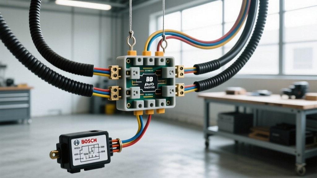
Introduction to the BB Auto Electrics Distribution System
When outfitting a modern overland vehicle, commercial van, or off-road truck with auxiliary lighting, winches, and onboard air compressors, the factory wiring harness is simply not designed to handle the additional amperage draw. This is where a heavy-duty auxiliary power distribution module becomes critical. This practical how-to guide details the complete installation of a BB Auto Electrics auxiliary fuse block and relay integration kit. Known for supplying robust, marine-grade automotive electrical components, the BB Auto Electrics distribution architecture allows you to safely route high-amperage circuits while maintaining clean, logical relay switching.
Pre-Installation Safety and Battery Disconnect Protocols
Before cutting, stripping, or routing a single wire, you must isolate the vehicle's primary electrical system. Disconnect the negative battery terminal first to prevent catastrophic short circuits. According to the ABYC E-11 DC Standards, any primary power feed originating directly from the battery must be protected by an overcurrent protection device within 7 inches (180mm) of the battery post. We will be integrating a 150A surface-mount MEGA fuse inline with our main 4 AWG feed to comply with this critical safety threshold.
Kit Inventory and Component Specifications
A proper installation requires the right materials. The BB Auto Electrics heavy-duty kit typically includes a 12-circuit ATC/ATO fuse block, a dedicated 6-stud ground bus bar, and a weather-sealed relay housing. Ensure you have the following supplementary materials:
- Main Power Feed: 4 AWG TXL (Cross-linked polyethylene) copper wire, Red.
- Main Ground Feed: 4 AWG TXL copper wire, Black.
- Accessory Outputs: 12 AWG GXL wire, assorted colors (Blue, White, Yellow).
- Trigger/Relay Wiring: 16 AWG primary wire.
- Terminals: Adhesive-lined marine heat-shrink ring terminals (3:1 shrink ratio).
- Fasteners: Stainless steel hardware and star washers for chassis grounding.
Phase 1: Main Battery Feed and MEGA Fuse Integration
The foundation of any auxiliary electrical system is the main power trunk. We will route a continuous length of Red 4 AWG TXL wire from the positive battery post to the main input stud of the BB Auto Electrics fuse block. Do not use splices or butt connectors for the main power trunk; a single continuous run minimizes resistance and voltage drop.
- Fuse Placement: Crimp a 4 AWG ring terminal onto one end of the Red wire and attach it to the positive battery post. Measure exactly 6 inches down the wire, cut the insulation, and crimp inline MEGA fuse holders onto both exposed ends.
- Routing: Route the 4 AWG wire through the firewall using an existing rubber grommet. Apply a silicone-based dielectric grease to the wire to prevent chafing against the firewall metal. Never run primary power wires parallel to data bus cables (CAN-Bus) to avoid electromagnetic interference (EMI).
- Termination: Crimp the final 4 AWG ring terminal and secure it to the 'BAT+' input stud on the BB Auto Electrics fuse block.
- Torque Specification: Tighten the M8 battery terminal nut to 8-10 Nm. Over-torquing can strip the lead post or crack the terminal casing.
Phase 2: Dedicated Ground Bus Bar Fabrication
Novice installers often daisy-chain grounds or bolt them to painted chassis brackets. This creates high-resistance ground loops, leading to dim lights and erratic relay behavior. The BB Auto Electrics kit includes a heavy-duty copper ground bus bar that must be bonded directly to bare chassis metal.
- Surface Preparation: Select a location near the fuse block. Use a wire wheel or 80-grit sandpaper to remove all paint, primer, and rust down to bare, shiny steel.
- Hardware Selection: Mount the bus bar using a stainless steel M6 bolt, a split lock washer, and a star washer. The star washer bites into the bare metal to ensure a permanent, low-resistance mechanical bond.
- Corrosion Prevention: Once torqued to 4-5 Nm, coat the entire ground connection in a lithium-based anti-corrosion paste or fluid film to prevent galvanic oxidation.
- Main Ground Trunk: Run the Black 4 AWG wire from the negative battery post to the primary M8 stud on the ground bus bar.
Phase 3: Relay Logic and Ignition Trigger Wiring
High-draw accessories (e.g., 50-inch LED light bars, onboard air compressors) must never be switched directly by a dashboard toggle switch. The switch will melt under the amperage load. Instead, we use the relay bay integrated into the BB Auto Electrics system. We will wire a standard ISO 7588 / Bosch-style 5-pin SPDT (Single Pole Double Throw) relay.
Bosch Relay Pinout Configuration
| Pin Number | Function | Wire Gauge & Color | Destination |
|---|---|---|---|
| 30 | Common Input (High Current) | 10 AWG Red | Fused output from BB Auto Electrics block |
| 87 | Normally Open (NO) Output | 10 AWG Blue | Accessory positive input (e.g., Light Bar) |
| 85 | Coil Ground | 16 AWG Black | Ground Bus Bar |
| 86 | Coil Trigger (+12V) | 16 AWG Yellow | Dashboard toggle switch / Ignition source |
| 87a | Normally Closed (NC) | Not Used | Insulate and tuck away |
Note: When the dashboard switch is flipped, it sends a low-amperage 12V signal to Pin 86. This energizes the internal electromagnetic coil, pulling the contactor from Pin 87a to Pin 87, allowing high current to flow from Pin 30 to your accessory. If you are switching highly inductive loads like compressor motors, install a flyback diode across pins 85 and 86 to suppress voltage spikes that can damage solid-state switches. For deeper insights into relay load management and wire insulation temperature ratings, refer to the SAE J1128 Low Tension Primary Cable specifications.
Wiring Specification and Routing Chart
Use the following reference chart to select the correct wire gauge based on the total amperage draw and the length of the wire run. Adhering to these specifications ensures your voltage drop remains below the 3% threshold recommended by the Blue Sea Systems Circuit Protection Guide.
| Accessory Load (Amps) | Wire Length (Under 10 ft) | Wire Length (10-20 ft) | Recommended Fuse (ATO/MAXI) |
|---|---|---|---|
| 5A - 10A | 14 AWG | 12 AWG | 15A ATO |
| 11A - 20A | 12 AWG | 10 AWG | 20A or 25A ATO |
| 21A - 35A | 10 AWG | 8 AWG | 40A MAXI |
| 36A - 50A | 8 AWG | 6 AWG | 60A MAXI |
Phase 4: Accessory Circuit Termination and Crimping
The most common point of failure in automotive electrical systems is a poorly executed crimp. Solder is generally discouraged in high-vibration automotive environments because it creates a rigid, brittle point that can snap under chassis flex. Instead, rely on high-quality mechanical crimps combined with adhesive-lined heat shrink.
- Stripping: Use a precision wire stripper calibrated for GXL/TXL insulation. Do not nick the copper strands, as this reduces the cross-sectional area and creates a localized hot spot.
- Crimping: Insert the stripped wire into the terminal barrel until it is flush with the inspection window. Use a ratcheting crimp tool to apply uniform pressure. The tool will not release until the crimp cycle is fully complete.
- Sealing: Apply heat evenly using a dedicated heat gun (not a lighter or torch). The adhesive lining must melt and extrude slightly from the edges of the terminal, forming a watertight seal against capillary action and moisture ingress.
- Fuse Assignment: Insert the corresponding ATO fuses into the BB Auto Electrics block. Always leave one or two blank, fused circuits reserved for future accessories to avoid tearing into the harness later.
Phase 5: System Validation and Voltage Drop Testing
Before reassembling the interior trim and engine bay covers, you must validate the integrity of the installation using a digital multimeter (DMM).
- Continuity Test: With the battery still disconnected, set your DMM to the continuity/ohms setting. Probe the ground wire at the accessory end and the bare chassis metal. You should read less than 0.5 ohms.
- Reconnect and Measure Resting Voltage: Reconnect the negative battery terminal. Measure the voltage at the battery posts. A healthy resting alternator/battery system should read between 12.4V and 12.7V.
- Voltage Drop Test (Positive Side): Turn on a high-draw accessory. Place the red probe on the positive battery post and the black probe on the accessory positive input terminal. A reading higher than 0.36V indicates excessive resistance in your power feed (likely a bad crimp or undersized wire).
- Voltage Drop Test (Negative Side): Place the black probe on the negative battery post and the red probe on the accessory ground casing. Again, any reading above 0.36V requires you to revisit your ground bus bar fabrication and star washer bite.
- Alternator Ripple Check: Start the engine and measure AC voltage across the battery terminals. Excessive AC ripple (above 50mV) can interfere with sensitive CAN-Bus modules connected to your auxiliary triggers. Ensure your main power routing is isolated from factory ECU harnesses.
Conclusion
Installing a BB Auto Electrics auxiliary fuse block transforms a chaotic nest of aftermarket add-on wires into a centralized, serviceable, and safe power distribution hub. By strictly adhering to proper AWG sizing, utilizing adhesive-lined marine terminals, and respecting torque specifications, you ensure your vehicle's electrical architecture can withstand the harshest off-road environments and daily driving vibrations alike. Always document your circuit assignments on the provided lid diagram to save hours of troubleshooting for the next technician or owner.