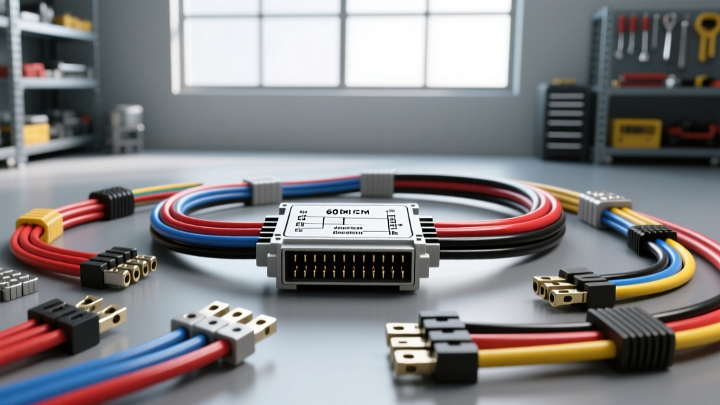
Introduction: The Critical Role of Bulkhead Connections in Modern Vehicles
The transition from simple point-to-point wiring to highly multiplexed, data-driven harnesses has fundamentally changed how we diagnose and repair vehicles. At the heart of this complexity is the Engine Control Module (ECM) bulkhead connector. Understanding the main harness connection in auto electrics requires a systematic approach to reading schematics, identifying terminal types, and verifying signal integrity. A single compromised pin in a 60-way high-density connector can cascade into multiple drivability faults, limp-mode triggers, and communication bus failures.
In this complete wiring diagram walkthrough, we will dissect a universal 60-pin TE Connectivity AMPSEAL ECM connector. This architecture is widely used across modern GM, Ford, and aftermarket standalone EFI systems. We will trace power distribution, sensor reference circuits, and high-speed CAN bus lines, providing the exact wire colors, AWG specifications, and diagnostic thresholds required for professional-level troubleshooting.
Decoding the Schematic: How to Read a Connection Auto Electics Diagram
Before probing a single wire, you must understand the schematic language used by OEM manufacturers. According to the Bosch Automotive Electrics and Electronics Handbook, modern diagrams utilize a grid-coordinate system alongside standardized node identifiers.
- Splice Packs (S100, S102): Indicate where multiple wires of the same circuit are joined inside the harness loom. A voltage drop here affects all downstream branches.
- Ground Distribution Blocks (G101, G102): Physical chassis ground points. A poor G101 connection will cause a 5V sensor reference to float, triggering false lean or rich codes.
- Connector Callouts (C105, C210): Represent the physical plastic housings. The diagram will show the connector from the wire-entry perspective, not the mating face.
Step-by-Step Walkthrough: 60-Pin ECM Main Harness Connection
The TE AMPSEAL 60-pin connector utilizes a three-row layout with a silicone interface mat to ensure IP67 waterproofing. The center 10mm retention bolt must be torqued to exactly 5 Nm (44 in-lbs) to fully seat the terminal pins against the ECM male blades.
Power and Ground Distribution (Pins 1-15)
The first block of pins is dedicated to high-current module wake-up and main power. Pin 1 receives constant battery voltage (Batt+) directly from the main under-hood fuse block. This circuit uses a 14 AWG Red wire to handle the continuous memory load and peak inrush current during ignition switch-on. Pin 2 is the Switched Ignition feed (14 AWG Pink), routed through the ignition relay.
Grounding is equally critical. Pins 10, 11, and 12 are dedicated ECM power grounds. These are 14 AWG Black wires that route to ground point G103 on the passenger side cylinder head. Never splice these grounds to a painted chassis bracket; they require a dedicated, bare-metal engine block connection to prevent ground-loop noise from the alternator.
Sensor Inputs and Actuator Outputs (Pins 16-45)
The middle section handles the 5-Volt Reference (5V REF) and low-level analog signals. Pin 20 provides the 5V REF (18 AWG Grey) to the Throttle Position Sensor (TPS) and Manifold Absolute Pressure (MAP) sensor. If this wire chafes and shorts to ground, the ECM will log a P0641 (Sensor Reference Voltage A Circuit) and disable electronic throttle control.
Sensor return signals, such as the TPS signal wire (18 AWG Blue), are highly susceptible to Electromagnetic Interference (EMI). In a proper connection auto electics layout, these low-voltage signal wires are twisted or routed away from high-current injector feeds. Injector drivers (Pins 30-37) utilize 16 AWG wires capable of handling the 4-to-6-amp peak saturation current required to open high-impedance fuel injectors.
CAN Bus and Data Lines (Pins 46-60)
Modern powertrains rely on High-Speed Controller Area Network (HS-CAN) for module-to-module communication. Pin 58 is CAN-High (20 AWG Green) and Pin 59 is CAN-Low (20 AWG Green/Black). These twisted-pair wires operate at 500 kbps. The ECM contains an internal 120-ohm terminating resistor. If the CAN bus wiring is compromised at this bulkhead connection, the terminating resistance of the network will drop below 45 ohms or spike above 90 ohms, resulting in a total network blackout and a U0100 (Lost Communication with ECM) code.
Wire Gauge, Color Codes, and Terminal Specifications
Proper terminal selection is non-negotiable. Using a standard brass terminal in an AMPSEAL housing will result in pin fretting and eventual open-circuit failures. Always use gold-plated, specific-gauge crimp terminals.
| Pin(s) | Circuit Name | Wire Color | AWG | Terminal Type | Function / Specification |
|---|---|---|---|---|---|
| 1 | Batt+ Constant | Red | 14 | Gold-Plated AMPSEAL | Module Memory / 12.6V Static |
| 2 | Ignition Feed | Pink | 14 | Gold-Plated AMPSEAL | Wake-up Signal / Relay Fed |
| 10-12 | Power Ground | Black | 14 | Gold-Plated AMPSEAL | Engine Block G103 / High Current |
| 20 | 5V Reference | Grey | 18 | Gold-Plated AMPSEAL | TPS/MAP Feed / 4.95V - 5.05V |
| 21 | TPS Signal | Blue | 18 | Gold-Plated AMPSEAL | 0.5V - 4.5V Analog Sweep |
| 25 | Sensor Ground | Black/Lt Blue | 18 | Gold-Plated AMPSEAL | Dedicated Low-Noise Ground |
| 30-37 | Injector Drivers | Varies | 16 | Gold-Plated AMPSEAL | Peak 6A / Hold 1A / PWM |
| 58 | CAN-High | Green | 20 | Gold-Plated AMPSEAL | HS-CAN / 2.5V - 3.5V Dominant |
| 59 | CAN-Low | Green/Black | 20 | Gold-Plated AMPSEAL | HS-CAN / 1.5V - 2.5V Dominant |
Real-World Troubleshooting: Voltage Drop and Pin Fretting
When diagnosing connection auto electrics failures at the ECM bulkhead, back-probing is preferred over piercing wire insulation, which invites moisture intrusion. According to SAE J1128 standards for low-tension primary cables, voltage drop limits must be strictly adhered to under loaded conditions.
Diagnostic Decision Tree: ECM Bulkhead Faults
- Symptom: Intermittent P0122 (TPS Circuit Low Voltage)
- Step 1: Measure 5V REF at Pin 20 with key-on, engine-off. Is it 4.95V - 5.05V?
- Step 2: If YES, measure TPS Signal at Pin 21 while sweeping the throttle. Does the voltage drop out momentarily?
- Step 3: If voltage drops out, perform a drag test on the female terminal at Pin 21 using a matching male test pin. If it slides in without resistance, terminal fretting has occurred.
- Fix: Extract the terminal using the proper TE Connectivity extraction tool (Part # 91968-1), crimp a new gold-plated terminal using the TE 58456-1 ratcheting crimp tool, and reseat.
- Symptom: U0100 (Lost Communication with ECM)
- Step 1: Disconnect the ECM and the TCM. Measure resistance across the CAN-H and CAN-L pins at the diagnostic OBD-II port (Pins 6 and 14).
- Step 2: Expected value is 60 ohms (two 120-ohm resistors in parallel).
- Step 3: If reading is 120 ohms, one terminating resistor is missing or the wire is broken. If reading is < 45 ohms, there is a short to ground or an extra module on the bus.
- Fix: Check the bulkhead connector for pushed-back pins on the Green/Green-Black wires. Ensure the silicone mat seal is fully seated to prevent terminal oxidation.
Expert Tips for Crimping and Sealing
The longevity of any connection in auto electics relies on the mechanical crimp and the environmental seal. When repairing wires leading to the 60-pin bulkhead, never use solder. Solder wicks up the wire strand, creating a rigid point that will snap under engine bay vibration. Always use an open-barrel, ratcheting crimp tool designed for the specific terminal series. Furthermore, the AMPSEAL connector relies on individual wire silicone plugs (mat seals). If a wire is removed, the corresponding silicone plug must be reinserted or replaced with a blanking plug to maintain the IP67 waterproof rating. Failure to do so will allow capillary action to draw water through the wire strands and directly into the ECM casing, destroying the module's internal circuit board.