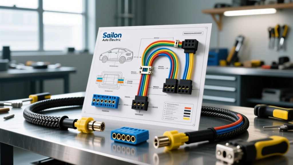
Architecture of Sailon Auto Electric Harness Assemblies
In the rapidly evolving landscape of electric vehicle (EV) conversions, 48V mild-hybrid upfits, and heavy-duty auxiliary power systems, the integrity of the wiring harness is paramount. Sailon Auto Electric has emerged as a critical supplier of high-current connectors, multi-pin signal housings, and custom wiring harness assemblies designed to withstand the harsh thermal and vibrational environments of modern automotive platforms. Unlike standard consumer-grade electronics connectors, Sailon Auto Electric components are engineered to meet stringent automotive specifications, focusing on terminal retention force, high-amperage thermal stability, and robust High Voltage Interlock Loop (HVIL) integration.
When integrating Sailon harnesses into a custom battery management system (BMS) or inverter architecture, technicians must move beyond basic continuity testing. A deep understanding of cold-weld crimp physics, electromagnetic interference (EMI) shielding protocols, and precise pinout configurations is required to prevent catastrophic failure modes such as terminal fretting, dielectric breakdown, or thermal runaway. This advanced technical guide details the exact specifications, crimping tolerances, and diagnostic procedures necessary for deploying Sailon Auto Electric systems in high-stakes automotive applications.
High-Current Terminal Crimping and AWG Specifications
The foundation of any high-current Sailon Auto Electric harness is the terminal-to-wire interface. In high-amperage circuits (such as the main traction battery to inverter feeds), a poor crimp introduces micro-ohms of resistance, which translates to severe localized heating under continuous load. According to the IPC-A-620 standard for cable and wire harness assemblies, a proper crimp must achieve a cold-weld state where the conductor strands and terminal barrel deform together, eliminating void spaces where oxidation could occur.
For Sailon’s high-current series terminals (typically rated for 120A to 250A continuous), technicians must utilize precise four-way indent or hexagonal crimp dies. The crimp must exhibit a proper conductor bellmouth (0.5mm to 1.0mm) to prevent the sharp edge of the terminal barrel from cutting into the conductor strands during vibration. Furthermore, the insulation barrel must securely grip the wire jacket without piercing it, providing essential strain relief.
Table: Sailon High-Current Series Terminal Crimp Specifications
| Wire Gauge (AWG) | Conductor Area (mm²) | Target Crimp Height (mm) | Target Crimp Width (mm) | Minimum Pull Force (N) |
|---|---|---|---|---|
| 4 AWG | 21.1 | 3.80 ± 0.05 | 4.60 ± 0.05 | 450 |
| 2 AWG | 33.6 | 4.90 ± 0.05 | 5.80 ± 0.05 | 700 |
| 1/0 AWG | 53.5 | 6.20 ± 0.05 | 7.40 ± 0.05 | 1100 |
| 2/0 AWG | 67.4 | 7.10 ± 0.05 | 8.50 ± 0.05 | 1450 |
Always verify crimp dimensions using a micrometer calibrated to 0.01mm. Relying solely on pull-force testing is insufficient for automotive applications; cross-sectional analysis is recommended for initial tooling validation to ensure the compression ratio falls between 15% and 20%, as mandated by SAE USCAR-2 performance specifications for automotive electrical connector systems.
HVIL and Low-Voltage Signal Pinout Configurations
Modern EV architectures utilize a High Voltage Interlock Loop (HVIL) to ensure that high-voltage connectors are fully seated before the main contactors close. If a connector is unplugged under load, the resulting DC arc can vaporize copper and destroy the inverter. Sailon Auto Electric multi-pin connectors integrate dedicated HVIL circuits that operate on a low-voltage (typically 5V or 12V) logic loop.
When wiring a Sailon 35-pin ECU/BMS interface connector, the HVIL pins are intentionally designed with a shorter physical length than the main power and ground pins. This ensures that during un-mating, the HVIL circuit breaks milliseconds before the high-voltage contacts separate, signaling the BMS to open the main contactors safely.
Sailon 35-Pin BMS/Inverter Interface Pinout (HVIL & CAN Sub-Section)
| Pin Number | Circuit Name | Wire Color | AWG | Function / Logic State |
|---|---|---|---|---|
| 1 | HVIL_OUT | Orange / White Stripe | 18 AWG (TXL) | Interlock Signal Out (5V Reference) |
| 2 | HVIL_IN | Orange / Black Stripe | 18 AWG (TXL) | Interlock Signal Return (Continuity Check) |
| 3 | CAN_H | Green | 20 AWG (STP) | CAN-Bus High (Dominant ~3.5V) |
| 4 | CAN_L | Green / Black Stripe | 20 AWG (STP) | CAN-Bus Low (Dominant ~1.5V) |
| 5 | Shield Drain | Bare Copper | 22 AWG | EMI Shield Ground (Terminate at ECU only) |
| 6 | Temp_Sense_NTC | Purple | 18 AWG (TXL) | Connector Thermal Sensor (10kΩ NTC) |
When terminating the HVIL circuit, use 18 AWG TXL (Cross-linked polyethylene) wire due to its superior thermal resistance and thin-wall profile, which aids in harness flexibility. The NTC temperature sensor on Pin 6 is a critical safety feature; if terminal fretting causes localized heating, the BMS will read the resistance drop in the NTC circuit and derate the inverter current before the connector reaches its thermal melting point.
EMI Shielding and CAN-Bus Routing Protocols
High-current switching in inverters and DC-DC converters generates severe electromagnetic interference (EMI). If Sailon Auto Electric signal harnesses are routed parallel to high-voltage traction cables without proper shielding, capacitive coupling will induce noise onto the CAN-bus lines, resulting in communication dropouts and phantom diagnostic trouble codes (DTCs).
To mitigate this, all Sailon signal harnesses carrying high-speed data (CAN, LIN, or resolver feedback) must utilize Shielded Twisted Pair (STP) cabling. The twist rate should be a minimum of 20 twists per meter to ensure that any induced electromagnetic fields cancel each other out. The metallic braid shield must be terminated using a 360-degree shield ring or pigtail to the connector backshell. Crucially, the shield drain wire (Pin 5 in the configuration above) must be grounded at the ECU/Inverter chassis only. Grounding both ends of the shield creates a ground loop, turning the shield into an antenna that exacerbates EMI issues rather than solving them.
Furthermore, maintain a minimum physical separation of 150mm between the Sailon high-voltage orange-jacketed power cables and the low-voltage signal harnesses. If a 90-degree crossing is unavoidable, ensure the cables intersect perpendicularly to minimize the surface area exposed to inductive coupling.
Advanced Diagnostic Decision Tree for Voltage Drop
Troubleshooting voltage drop in a Sailon Auto Electric high-current harness requires moving beyond simple multimeter resistance checks. A standard digital multimeter (DMM) applies less than 10 milliamps during a resistance test, which is insufficient to detect micro-arcing or oxide layers that only manifest under high load. Instead, perform a loaded millivolt drop test using a high-precision DMM (such as a Fluke 87V) while the system is under operational load.
Millivolt Drop Diagnostic Sequence
- Baseline Measurement: With the system drawing nominal continuous current (e.g., 80A for a DC-DC converter), place the positive DMM probe on the battery-side busbar and the negative probe on the inverter-side terminal of the Sailon connector. A healthy 2/0 AWG circuit should exhibit a voltage drop of less than 10mV per meter of cable length.
- Isolate the Connector: If the total circuit drop is high (e.g., >50mV), move the probes directly across the Sailon connector mating interface (from the wire crimp barrel on the source side to the wire crimp barrel on the load side). A drop exceeding 5mV across the connector indicates internal terminal degradation, loss of normal force (spring tension), or fretting corrosion.
- Thermal Validation: Use a FLIR thermal imaging camera to scan the harness under peak load. Look for thermal gradients. A healthy Sailon connector will show a uniform temperature profile. A localized hotspot (delta T > 10°C above ambient wire temperature) confirms high resistance at the crimp barrel or mating interface.
- Terminal Extraction and Inspection: If a hotspot is detected, safely depower the system, discharge the inverter capacitors, and extract the terminal using the correct Sailon wedge removal tool. Inspect the male and female tines for galvanic corrosion or galling. Never apply dielectric grease to high-current Sailon terminals; the grease can trap heat and attract abrasive particulates. Instead, use a dedicated electrical contact cleaner and verify the terminal retention force with a calibrated pull gauge.
By adhering to these advanced integration, crimping, and diagnostic protocols, automotive electrical engineers can ensure that Sailon Auto Electric harnesses deliver the reliability, safety, and performance required for next-generation vehicle architectures. For further safety guidelines regarding high-voltage automotive systems, refer to the SAE J2344 recommended practices for EV safety.