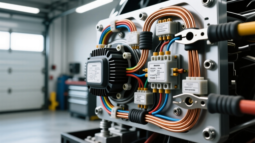
South Texas Heat and Heavy-Duty Charging System Demands
Operating a vehicle in the Rio Grande Valley presents unique thermal and electrical challenges. With ambient summer temperatures routinely exceeding 100°F, engine bay temperatures can easily surpass 180°F. Under these conditions, standard OEM charging systems—typically rated between 130A and 150A—suffer from severe thermal derating. When you add the continuous load of heavy-duty air conditioning compressors, high-amperage cooling fans, and aftermarket accessories, the factory alternator quickly becomes the weakest link in the vehicle's electrical architecture.
Leading regional specialists, such as Escobar Auto Electric in Weslaco, Texas, have developed rigorous installation methodologies to combat these exact failure modes. Their approach to high-output alternator retrofits and dual-battery architectures prioritizes thermal management, voltage drop mitigation, and precise regulator pinout routing. This practical how-to installation guide breaks down the professional-grade wiring techniques required to upgrade a light-duty truck or SUV to a 200A+ high-output charging system, utilizing the heavy-duty standards observed in South Texas shops.
Phase 1: High-Output Alternator Selection and Thermal Derating
Before cutting any wire, it is critical to select an alternator that can sustain high output in extreme heat. Most OEM-style alternators lose up to 20% of their rated output when casing temperatures exceed 200°F. For a reliable upgrade, source a high-ambient Denso or Bosch heavy-duty unit featuring a dedicated rear-bearing cooling fan and oversized diode rectifiers.
When installing a 220A Denso unit, verify the pulley ratio. Many high-amp alternators require a smaller crankshaft pulley or a larger alternator pulley to achieve a 3:1 ratio, ensuring the rotor spins fast enough to reach peak output at idle (typically 1,800 to 2,200 alternator RPM). If the pulley ratio is too low, the alternator will rely heavily on the battery to supplement loads at idle, leading to premature stator burnout.
Phase 2: Main Charge Cable Architecture (B+ Circuit)
The most common point of failure in high-amp upgrades is the main charge wire (B+ terminal to the positive battery post). Factory wiring harnesses are engineered for the specific resistance and current limits of the OEM alternator. Pushing 220A through a factory 6 AWG or 4 AWG wire will result in catastrophic voltage drop, excessive heat generation, and potential electrical fires.
Following the rigorous standards utilized by Escobar Auto Electric in Weslaco, the main charge cable must be upgraded to SGT (SGT battery cable) or fine-strand welding wire. This flexible, high-strand-count copper wire handles high DC current with significantly less resistance and heat buildup than rigid THHN wire.
Charge Wire Sizing and Fusing Specification Chart
| Alternator Peak Output | Min. Wire Gauge (Up to 5 ft) | Min. Wire Gauge (5-10 ft) | Recommended MEGA/ANL Fuse | Terminal Crimp Die |
|---|---|---|---|---|
| 150A - 170A | 4 AWG SGT | 2 AWG SGT | 200A MEGA | 4 AWG Hex |
| 180A - 210A | 2 AWG SGT | 1/0 AWG SGT | 250A MEGA | 2 AWG Hex |
| 220A - 250A+ | 1/0 AWG SGT | 2/0 AWG SGT | 300A MEGA | 1/0 AWG Hex |
Note: Always use adhesive-lined, dual-wall polyolefin heat shrink over copper lug terminals. The inner adhesive layer melts and seals the wire strands, preventing copper oxidation and electrolytic corrosion caused by battery acid fumes.
Phase 3: Denso 4-Pin Regulator Wiring and Sense Routing
Modern high-output alternators utilize an internal voltage regulator controlled by a multi-pin connector. The Denso 4-pin (Sumitomo HM 090 series) connector is the industry standard for many Toyota, Lexus, and heavy-duty aftermarket applications. Incorrectly wiring this harness is the primary reason upgraded alternators fail to reach peak voltage.
- Pin 1 (IG - Ignition): Requires a clean, switched 12V source. This wakes up the regulator. Route this to a dedicated ignition relay circuit, never directly to a high-draw accessory switch.
- Pin 2 (L - Lamp): Connects to the dashboard charge indicator lamp. If your vehicle uses a CAN-bus system for dash warnings, you must install a 470-ohm pull-up resistor to simulate the bulb load, or the regulator will default to a limp-mode voltage of 13.2V.
- Pin 3 (S - Sense): This is the most critical pin. The Sense wire tells the regulator what the actual voltage is at the battery. If you wire the Sense pin to the alternator's B+ terminal, the regulator will not compensate for the voltage drop across the 1/0 AWG cable and the MEGA fuse. The Sense wire (12 AWG TXL) must be routed directly to the positive battery post, fused inline with a 5A blade fuse.
- Pin 4 (F - Field): Provides a duty-cycle square wave output to the ECU for load management. If your aftermarket ECU does not require this, cap and seal the pin cavity to prevent moisture ingress.
For authoritative wiring schematics and terminal extraction procedures, refer to the Denso Automotive Service Manuals or consult SAE J1141 standards for heavy-duty electrical installations.
Phase 4: Overcurrent Protection and Grounding Architecture
A high-amp alternator can output enough current to weld metal if a short circuit occurs. According to Littelfuse MEGA fuse specifications, the main overcurrent protection device must be rated at 125% to 150% of the alternator's maximum continuous output. For a 220A alternator, a 300A MEGA fuse installed within 7 inches of the positive battery terminal is mandatory. Do not use standard AGU fuses, as their internal element construction cannot safely interrupt high DC fault currents without shattering the glass housing.
Ground Strap Upgrades
Electrical current only flows as well as it can return to the source. Upgrading the positive side of the circuit without upgrading the ground side will create a bottleneck. Remove the factory braided ground straps. Clean the engine block and chassis mounting points down to bare metal using a stainless steel wire brush. Install a minimum 2 AWG braided copper ground strap from the alternator casing to the engine block, and another from the engine block to the chassis rail. Torque the M8 grounding bolts to 22 Nm, and apply a dielectric grease coating after torquing to seal out moisture and prevent galvanic corrosion.
Phase 5: Validation, Load Testing, and Ripple Analysis
Professional installation is only complete after rigorous empirical testing. Following the methods championed by top-tier diagnostics centers like Escobar Auto Electric in Weslaco, the final validation requires a carbon pile tester and an automotive oscilloscope.
- Static Voltage Test: With the engine running and no loads applied, measure voltage directly at the battery posts. It should read between 14.2V and 14.6V.
- Carbon Pile Load Test: Apply a load equal to 80% of the alternator's rated output (e.g., 176A for a 220A unit) while the engine is at 2,000 RPM. The system voltage must not drop below 13.0V. Monitor the 1/0 AWG charge cable with an infrared thermometer; a temperature rise of more than 40°F above ambient indicates poor crimping or insufficient wire gauge.
- AC Ripple Test: Connect an oscilloscope to the battery. Set the coupling to AC and the scale to 100mV/div. A healthy high-output alternator with intact diode rectifiers will show an AC ripple of less than 50mV. A ripple exceeding 100mV indicates a blown diode or excessive stator harmonic distortion, which will destroy sensitive vehicle electronics over time.
By adhering to these rigorous wire sizing, pinout routing, and validation protocols, you ensure the vehicle's charging system can withstand the brutal thermal and electrical demands of South Texas driving, mirroring the reliability standards of the region's best auto electric specialists.