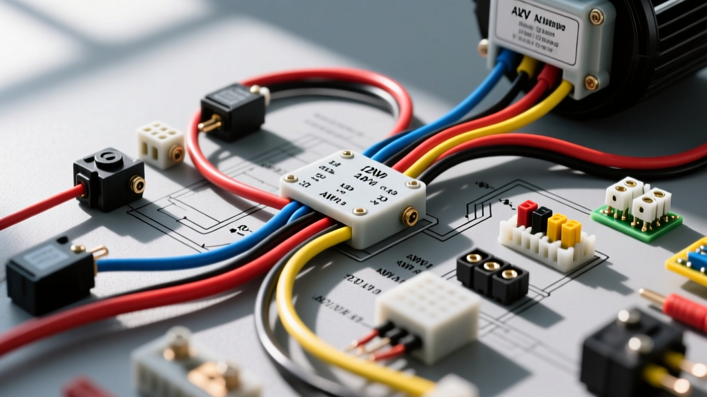
The Evolution of AC Auto Electrical Systems
The transition from internal combustion engines to electric vehicle (EV) swaps, restomods, and heavy-duty auxiliary builds has fundamentally changed how we approach climate control. In a traditional vehicle, the air conditioning compressor is belt-driven, requiring only a simple electrical clutch coil. However, modern AC auto electrical architectures rely on fully electric, hermetically sealed compressors. When selecting an electric compressor for a custom build, fabricators and technicians face a critical decision: utilize a 12V DC system or integrate a High-Voltage (HV) 200V-400V DC compressor. This guide breaks down the wiring specifications, circuit protection requirements, and real-world failure modes of both AC auto electrical pathways to help you select the right architecture for your project.
12V DC Electric Compressors: Wiring and Circuit Protection
12V DC electric compressors are the most accessible option for traditional restomods and 12V auxiliary setups. Because they operate on standard vehicle voltage, they do not require specialized high-voltage safety interlocks or expensive shielded cabling. However, the trade-off is massive current draw. A typical 12V DC compressor (such as those based on Sanden or generic hermetic designs) requires between 45A and 65A of continuous current, with Locked Rotor Amps (LRA) spiking up to 120A during startup.
Harnessing and Circuit Protection Specs
Due to the high amperage, standard automotive relays and ATC blade fuses are entirely inadequate and present a severe fire hazard. Proper AC auto electrical design for 12V systems mandates heavy-duty components:
- Wire Gauge: Minimum 2 AWG TXL (cross-linked) stranded copper for runs up to 15 feet. If the run exceeds 15 feet, upgrade to 1/0 AWG to prevent voltage drop.
- Wire Colors: Red for main +12V power, Black for chassis ground, and Yellow or Blue for the 12V logic trigger.
- Circuit Protection: An 80A or 100A MEGA fuse (such as those specified by Littelfuse automotive standards) mounted within 7 inches of the battery positive terminal.
- Switching: A heavy-duty contactor (e.g., Gigavac GX14 or Albright SW180) rated for 100A+ continuous DC load. Standard Bosch-style 30A relays will weld their contacts shut under this load.
- Terminations: Ring terminals must be hex-crimped using a calibrated tool, then sealed with dual-wall, adhesive-lined heat shrink to prevent moisture ingress and subsequent galvanic corrosion.
High-Voltage (HV) Electric Compressors: Architecture and Safety
For dedicated EV conversions utilizing high-voltage battery packs (typically 200V to 400V DC), HV electric compressors are the superior choice. Sourced from OEMs like Denso or Nissan, these compressors feature internal inverters that convert DC to 3-phase AC to drive the motor. Because power equals voltage multiplied by current (P=VI), operating at 300V drastically reduces the amperage draw. A 3kW HV compressor draws only 10A at 300V, allowing for much smaller, albeit highly specialized, wiring.
HV Safety, Cabling, and Pinout Configurations
Working with HV AC auto electrical components requires strict adherence to safety protocols outlined in standards like SAE J2344 (Guidelines for Electric Vehicle Safety). The cabling and connector architecture is vastly different from 12V systems.
- Power Cabling: 16 AWG or 14 AWG shielded, high-voltage orange cable (SAE J1673 compliant). The shielding must be grounded at the inverter/battery end to prevent electromagnetic interference (EMI) from disrupting CAN-bus signals.
- Connectors: OEM Sumitomo or Amphenol HVSL series connectors with integrated High Voltage Interlock Loop (HVIL) pins.
- Typical 4-Pin OEM Compressor Pinout:
- Pin 1 (HV+): High Voltage Positive (Orange cable).
- Pin 2 (HV-): High Voltage Negative (Orange cable with black stripe or distinct shielding).
- Pin 3 (12V Enable): 12V logic wake signal (Standard 18 AWG wire).
- Pin 4 (HVIL/CAN): Interlock loop return or CAN-Low signal to verify connector seating before the internal contactor closes.
When fabricating HV harnesses, technicians must use specialized indent crimp dies designed for HV terminals. A poor crimp on an HV compressor circuit can lead to localized heating, melting the connector housing and causing a catastrophic isolation fault.
Comparison Matrix: AC Auto Electrical System Specifications
The following table provides a direct comparison to assist in component selection and harness fabrication planning.
| Specification | 12V DC Compressor | High-Voltage (300V) Compressor | Traditional Belt-Driven Clutch |
|---|---|---|---|
| Operating Voltage | 12V - 14.4V DC | 200V - 400V DC | 12V - 14.4V DC |
| Continuous Amp Draw | 45A - 65A | 5A - 15A | 3A - 5A |
| Main Power Wire (AWG) | 2 AWG or 1/0 AWG TXL | 16 AWG or 14 AWG Shielded HV | 14 AWG or 16 AWG GXL |
| Circuit Protection | 80A - 100A MEGA Fuse | Integrated HV Inverter Protection / HV Pyro Fuse | 15A ATC Blade Fuse |
| Switching Mechanism | 100A+ DC Contactor | CAN-bus / 12V Logic Enable | Standard 30A ISO Relay |
| Safety Interlocks | None (Standard DC safety) | HVIL Loop required | None |
Traditional Clutch Coils: The Baseline Comparison
While electric compressors dominate the EV and restomod space, understanding the traditional belt-driven clutch coil is essential for baseline diagnostics. A standard Sanden SD7 or Selco clutch coil draws roughly 3.5A to 4.5A at 14V. The wiring harness requires only 14 AWG GXL wire, protected by a 15A ATC fuse, and switched via a standard Bosch JD1914 30A relay. The primary failure mode in these legacy AC auto electrical systems is the degradation of the clutch coil winding insulation, leading to a short to ground, or the failure of the relay contacts due to inductive voltage spikes when the clutch disengages. Installing a flyback diode (e.g., 1N4004) across the clutch coil terminals is a proven method to suppress these spikes and protect the vehicle's ECU and relay contacts.
Real-World Failure Modes and Diagnostics
When troubleshooting modern AC auto electrical systems, technicians must look beyond simple continuity tests. The internal inverters of electric compressors are highly sensitive to power quality and isolation integrity.
12V System Voltage Drop and LVL Faults
The most common failure in 12V electric compressor installations is not a broken wire, but excessive voltage drop. The internal inverter requires a minimum threshold (often around 10.5V) to operate. If the 2 AWG power wire or the chassis ground path has high resistance, the voltage at the compressor terminals may drop below this threshold during the high-current startup phase. This triggers a Low Voltage Lockout (LVL) fault, causing the compressor to shut down immediately. Diagnostic Step: Perform a dynamic voltage drop test. With the system attempting to start, measure the voltage drop across the positive cable and the ground cable independently. A drop greater than 0.2V per cable indicates undersized wiring, poor crimps, or corroded battery terminals.
HV Isolation Faults and Chafing
In high-voltage setups, the vehicle's Battery Management System (BMS) constantly monitors the isolation resistance between the HV DC bus and the vehicle chassis. If the orange shielded cable routing to the AC compressor rubs against a sharp chassis edge, the shielding and insulation can wear through. Even if the HV+ and HV- conductors do not short to ground, the BMS will detect a drop in megohm isolation resistance and trigger a hard shutdown of the entire HV system, disabling the vehicle. Diagnostic Step: Use a high-voltage insulation tester (Megger) set to 500V or 1000V to test the isolation resistance of the compressor harness with the compressor disconnected. Refer to EV West technical documentation and OEM service manuals for specific megohm thresholds, which typically require a minimum of 500 ohms per volt (e.g., 150kΩ for a 300V system).
Final Selection Verdict
Choosing the correct AC auto electrical architecture depends entirely on your vehicle's primary power source. If you are building a traditional V8 restomod or a heavy-duty auxiliary truck setup with a massive 12V dual-alternator system, a 12V DC compressor with a properly engineered 2 AWG harness and MEGA fusing is the most logical path. However, if you are executing a dedicated EV conversion with a 300V+ battery pack, bypassing the 12V system and utilizing an OEM High-Voltage compressor is vastly superior. It reduces low-voltage parasitic draw, eliminates the need for massive cabling, and leverages the native efficiency of high-voltage DC architectures. Regardless of the path chosen, respecting wire gauge specifications, crimp standards, and circuit protection protocols is non-negotiable for a safe, reliable climate control system.