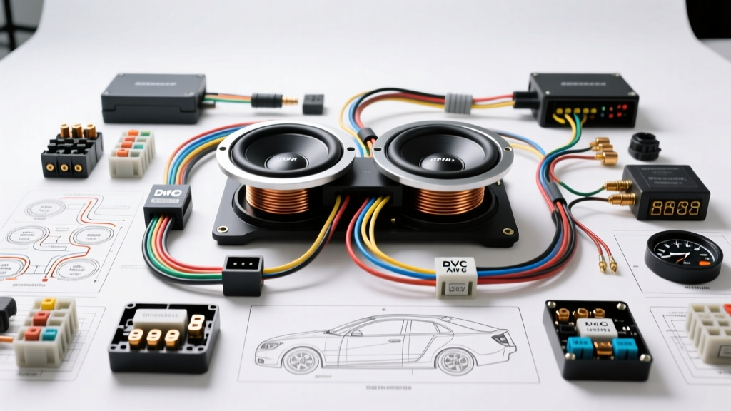
Pre-Installation: Calculating Impedance and AWG Requirements
Proper car sub wiring begins long before you strip a single cable. The foundation of a reliable bass system relies on matching your amplifier's RMS output to the subwoofer's voice coil impedance, and selecting the correct American Wire Gauge (AWG) to prevent voltage drop and thermal throttling. According to the Mobile Electronics Certified Professional (MECP) guidelines, undersized power wire is the leading cause of amplifier clipping and subwoofer voice coil burnout.
Always use Oxygen-Free Copper (OFC) rather than Copper-Clad Aluminum (CCA). CCA wire has higher DC resistance, requiring you to step up one full AWG size to carry the same current safely.
AWG Power Wire Sizing Chart (OFC Standard)
| Total System RMS Wattage | 0-16 ft Run | 16-24 ft Run | Main Fuse Rating (AGU/ANL) |
|---|---|---|---|
| Up to 400W | 8 AWG | 4 AWG | 40A - 60A |
| 400W - 1000W | 4 AWG | 2 AWG | 80A - 120A |
| 1000W - 1500W | 1/0 AWG | 1/0 AWG | 150A - 200A |
| 1500W - 2500W | 1/0 AWG | 2/0 AWG | 250A - 300A |
| 2500W+ | 2/0 AWG | 3/0 AWG | 350A+ (ANL Class T) |
Source reference: CTA-2015 Mobile Electronics Cabling Standards.
Step 1: Routing Power, Ground, and Remote Cables
Battery and Firewall Routing
Disconnect the negative battery terminal before beginning. Route your main power cable from the battery to the amplifier location (typically the trunk or rear cabin). Use an existing firewall grommet—never drill through bare metal without a rubber firewall bushing to prevent insulation chafing and catastrophic short circuits. Secure the cable every 18 inches using plastic loom clamps or zip ties, keeping it on the opposite side of the vehicle from any high-current alternator lines or factory ECU harnesses to prevent Electromagnetic Interference (EMI).
Establishing a True Chassis Ground
The ground wire is just as critical as the power wire. Keep your ground run under 3 feet. Locate a structural bolt on the vehicle chassis (not a seatbelt anchor or thin sheet metal). Sand away all paint, primer, and rust down to bare steel using 80-grit sandpaper. Crimp an 8mm or 10mm OFC ring terminal onto your ground wire using a hex-crimp tool (never solder high-current ground lugs, as solder can melt under thermal load and crack under vibration). Secure the bolt with a star washer and torque to factory specifications (typically 25-35 Nm). Coat the exposed metal with dielectric grease to prevent oxidation.
Step 2: DVC vs. SVC Car Sub Wiring Configurations
The most complex part of car sub wiring is configuring the speaker wire to match the amplifier's stable impedance. Most modern Class D monoblock amplifiers are optimized for a 1-ohm or 2-ohm final load.
Wiring a Dual 4-Ohm Voice Coil (DVC) Subwoofer
- Parallel Wiring (2-Ohm Final Load): Connect the amplifier's positive terminal to both positive voice coil terminals. Connect the amplifier's negative terminal to both negative voice coil terminals. Finally, bridge the remaining positive and negative terminals on the subwoofer together using a short jumper wire. This halves the impedance (4 / 2 = 2 ohms).
- Series Wiring (8-Ohm Final Load): Connect amp positive to coil 1 positive. Bridge coil 1 negative to coil 2 positive. Connect amp negative to coil 2 negative. This doubles the impedance (4 + 4 = 8 ohms), typically used for bridging 2-channel amplifiers.
Wiring a Dual 2-Ohm Voice Coil (DVC) Subwoofer
- Parallel Wiring (1-Ohm Final Load): Wire exactly like the DVC 4-ohm parallel configuration. This results in a 1-ohm load, ideal for high-output monoblocks designed for SPL (Sound Pressure Level) competitions.
- Series Wiring (4-Ohm Final Load): Wire exactly like the DVC 4-ohm series configuration. This yields a safe 4-ohm load, perfect for running two DVC 2-ohm subs in parallel on a 2-ohm stable amp.
Before connecting the speaker wire to the amplifier, set your digital multimeter to the 200-ohm resistance setting. Place the probes across the amplifier's positive and negative speaker terminals. A DVC 4-ohm sub wired in parallel should read approximately 2.0 ohms. If it reads infinite (OL), you have an open circuit or broken jumper. If it reads near 0.0 ohms, you have a dead short. Use 12 AWG or 10 AWG multi-strand OFC speaker wire for all subwoofer connections. Secure the spade terminals or bare wire into the amplifier's set-screw terminals and tighten to roughly 35-45 in-lbs to prevent arcing.
Step 3: Signal Integration (RCA vs. High-Level Inputs)
If you are using an aftermarket head unit, run shielded twisted-pair RCA cables from the 'SUB' or 'REAR' pre-outs to the amplifier. Keep RCA cables routed strictly down the center console or opposite side of the vehicle from the power wire to avoid alternator whine. Twisting the RCA cables around each other every few inches further rejects common-mode EMI noise.
If integrating with a factory OEM amplifier or head unit without pre-outs, you must use a Line Output Converter (LOC) or an amplifier with built-in high-level inputs. Splice into the factory rear speaker wires (typically Left Rear: White/White-Black, Right Rear: Purple/Purple-Black in standard Chrysler/Jeep harnesses, though a multimeter phase test is mandatory). Set the LOC's gain potentiometer using an oscilloscope or digital multimeter to match the amplifier's input sensitivity (usually between 2V and 5V RMS).
Step 4: Remote Turn-On and Fuse Placement
The remote turn-on wire (typically 18 AWG blue with a white stripe) signals the amplifier to power up when the head unit turns on. Connect this to the head unit's 'System Remote Control' or 'Amp Turn-On' lead. If using a factory radio, tap into a 12V+ accessory circuit at the fuse box (like a windshield wiper or 12V socket fuse) using an add-a-circuit fuse tap, ensuring the circuit only powers on with the ignition in the 'ACC' or 'RUN' position.
Critical Safety Step: Install the main power fuse (AGU, ANL, or Class T) within 18 inches of the positive battery terminal. This protects the entire vehicle from a fire in the event the main power cable shorts to the chassis before it reaches the amplifier's internal fuses.
Troubleshooting Common Car Sub Wiring Faults
| Symptom | Probable Cause | Diagnostic Fix |
|---|---|---|
| Subwoofer plays, but bass is extremely weak or 'hollow' | Out-of-phase speaker wiring | Reverse the positive and negative speaker wires at one voice coil. Ensure both coils are wired identically. |
| Amplifier Protect Mode light flashes on heavy bass hits | Voltage drop or Impedance mismatch | Check battery voltage at the amp terminals under load (should stay above 11.5V). Verify subwoofer impedance with a multimeter. |
| High-pitched alternator whine that revs with engine RPM | Ground loop or EMI induction | Ensure amp ground and head unit ground share the same chassis potential. Separate RCA cables from power cables by at least 18 inches. |
| Amp turns on, but no audio signal reaches sub | Blown RCA ground shield or LOC failure | Test RCA cables with a known good source. Check LOC gain settings and verify high-level input splices are making solid copper-to-copper contact. |
Final System Tuning and Verification
Once all car sub wiring connections are verified and double-checked with a multimeter for continuity and short circuits, reconnect the vehicle battery. Turn the head unit volume to 75% of its maximum unclipped output. Adjust the amplifier's low-pass filter (LPF) to roughly 80Hz, matching the Crossover settings recommended by audio experts. Slowly increase the amplifier's gain control until you hear slight distortion, then back it off by 10%. Finally, adjust the bass boost and subsonic filter (set to 5Hz below your enclosure's tuning frequency) to protect the subwoofer from mechanical over-excursion.
For further reading on mobile electrical safety and wire gauge standards, refer to the Mobile Electronics Certification Program (MECP) installation guidelines and the CTA-2015 Mobile Electronics Cabling Standards. Proper execution of these steps ensures your system delivers clean, powerful bass without compromising your vehicle's electrical integrity.