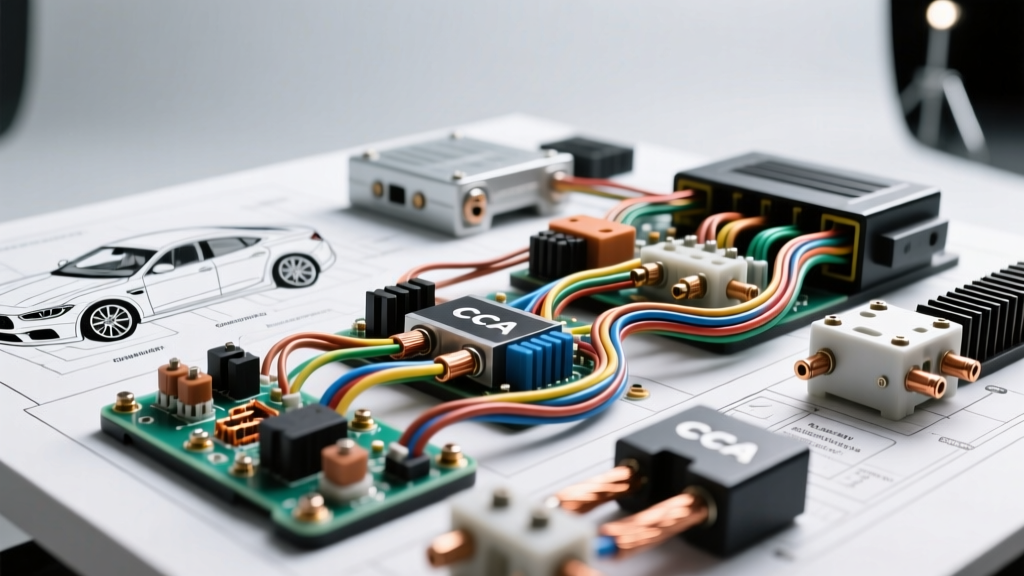
Why Professional Car Audio Wiring Help is a Matter of Safety
When enthusiasts first seek out car audio wiring help, the focus is almost entirely on making the system produce sound. However, improper automotive electrical integration doesn't just result in poor sound quality or annoying alternator whine—it creates severe fire hazards and can destroy your vehicle's ECU. Modern vehicles utilize complex CAN bus networks and low-tolerance alternators; treating your car's electrical system like a home stereo is a recipe for catastrophic failure.
As an automotive electrical specialist, I have inspected hundreds of aftermarket stereo installations. Below, we break down the five most dangerous and common wiring mistakes, providing the exact specifications, wire colors, and hardware requirements needed to do the job safely and correctly.
Mistake 1: The 'Anywhere on the Chassis' Grounding Fallacy
The most frequent cause of amplifier clipping, thermal shutdown, and ground loop noise is a poor chassis ground. Many beginners assume that any metal surface under the carpet is a valid ground. This is false. Modern automotive manufacturing uses an E-coat (electro-coat) primer and thick seam sealers that act as electrical insulators.
The Correct Grounding Procedure:
- Locate Structural Steel: Find a solid, welded chassis point or a factory seat belt bolt location. Never use thin sheet metal or self-tapping screws, which can strip and create high-resistance arcs.
- Remove the E-Coat: Use a rotary tool with a sanding drum or 80-grit sandpaper to strip the paint, primer, and rust down to bare, shiny steel. The contact area should be slightly larger than your ring terminal.
- Hardware Selection: Use an M8 or M10 stainless steel machine screw with a matching flange nut and a star lock washer. The star washer bites into the bare metal to ensure a gas-tight connection that resists vibration.
- Torque and Seal: Torque the M8 bolt to 15-20 Nm. Apply a dab of dielectric grease or anti-oxidant paste (like Noalox) over the exposed metal to prevent galvanic corrosion, then seal the entire area with liquid electrical tape.
Mistake 2: Undersizing Power Wire and the CCA Trap
Not all copper wire is created equal. The market is flooded with Copper-Clad Aluminum (CCA) wire, which is significantly cheaper but has roughly 30% less electrical conductivity than true Oxygen-Free Copper (OFC). According to the SAE J1128 Low Tension Primary Cable Standard, automotive wire must handle specific thermal loads. CCA wire runs much hotter under heavy amperage draws, leading to voltage drops that starve your amplifiers and melt insulation.
If you must use CCA wire due to budget constraints, you must increase the wire gauge by at least one to two AWG sizes compared to OFC specifications. Furthermore, never rely on the wattage printed on the amplifier box; calculate wire size based on the total RMS wattage and system efficiency (typically 50% for Class AB, 75% for Class D).
OFC vs. CCA Wire Gauge Sizing Chart (Up to 15ft Run)
| Total System RMS Wattage | Max Current Draw (Class D) | Required OFC AWG | Required CCA AWG |
|---|---|---|---|
| 500W | 45A | 8 AWG | 4 AWG |
| 1000W | 90A | 4 AWG | 1/0 AWG |
| 1500W | 135A | 1/0 AWG | 2/0 AWG |
| 2500W+ | 225A+ | 2/0 AWG | 4/0 AWG |
Mistake 3: Confusing the Remote Turn-On Pins (ISO 10487)
When integrating an aftermarket head unit with factory or aftermarket amplifiers, the remote turn-on wire dictates when the amp powers up. Standard ISO 10487 Connector A (Power) features two blue wires that are frequently confused:
- Blue Wire (Pin 5): Power Antenna. This wire outputs 12V only when the AM/FM radio tuner is active. If you wire your amplifier remote to this pin, the amp will shut off the moment you switch to Bluetooth, USB, or a CD, causing massive bass dropouts.
- Blue/White Stripe Wire (Pin 7): Amplifier Remote Turn-On. This outputs a steady 12V signal whenever the head unit is powered on, regardless of the source.
Expert Warning: The remote turn-on circuit on most head units is capped at 300mA. If you are triggering multiple amplifiers, a digital signal processor (DSP), and a line driver, you will exceed this limit and fry the head unit's internal switching transistor. Always use a 12V 30A automotive relay (Bosch-style 5-pin) triggered by the Blue/White wire to switch the main 12V constant battery line to your amplifier rack.
Mistake 4: Fusing Placement and Hardware Selection
The main power fuse is not there to protect your amplifier; it is there to protect your car from burning to the ground in the event of a short circuit. The Mobile Electronics Certification Program (MECP) strictly mandates that the main system fuse must be installed within 18 inches (45.7 cm) of the positive battery terminal. Any length of unfused wire running through the firewall is a dead short waiting to happen.
Furthermore, avoid cheap glass AGU fuses for high-current systems. Glass AGU fuses are prone to shattering from engine bay vibrations and often feature weak end-cap welds that melt under continuous high-amperage loads. For any system drawing over 60A, use a Bussmann ANL or Class-T fuse with a solid block holder, mounted securely to the chassis near the battery.
Mistake 5: RCA Routing and Inductive Coupling
Alternator whine—a high-pitched squeal that rises and falls with engine RPM—is caused by electromagnetic interference (EMI) or ground loops. The most common physical cause is running low-voltage RCA signal cables parallel to high-current 12V power cables. The magnetic field generated by the alternator's charging current induces a parasitic voltage into the RCA shields.
The Fix: Always route power and ground cables down the passenger side of the vehicle, and RCA/speaker signal cables down the driver's side. If the physical layout of your trunk or hatch requires the cables to cross paths, they must cross at a strict 90-degree angle to minimize inductive coupling. Never zip-tie RCA cables to power wires.
Troubleshooting Decision Tree: Audio Electrical Failures
Use this diagnostic tree when your system exhibits abnormal behavior after installation:
- Symptom: Amplifier 'Protect' Mode Light Illuminates Immediately
- Cause 1: Shorted speaker wire touching chassis ground. (Fix: Check all speaker terminals with a multimeter for continuity to ground).
- Cause 2: Severe voltage drop at the amp. (Fix: Measure DC voltage at the amp's BATT and GND terminals while cranking. If below 10.5V, upgrade ground wire or add a secondary battery).
- Symptom: Loud 'Pop' Through Subwoofers When Turning Off Ignition
- Cause: Amplifier is turning off before the DSP or head unit stops sending audio signal. (Fix: Install a relay with a delay timer on the remote turn-on circuit, or adjust DSP boot/shutdown sequences).
- Symptom: System Works, But Head Unit Resets When Bass Hits
- Cause: Voltage sag on the 12V Constant (Yellow) wire. (Fix: Ensure the yellow wire is tied directly to the battery via a dedicated fused line, not tapped into a thin factory cigarette lighter circuit).
Final Thoughts on Automotive Electrical Safety
Proper car audio installation requires respect for automotive electrical engineering. By utilizing OFC wiring, adhering to strict grounding protocols, and understanding standard pinouts like the ISO 10487 harness, you ensure your system sounds incredible and remains safe for years to come. For further reading on interface modules and factory integration, consult PAC Audio Interface Documentation to ensure you are properly managing CAN bus data signals without back-probing sensitive vehicle modules.