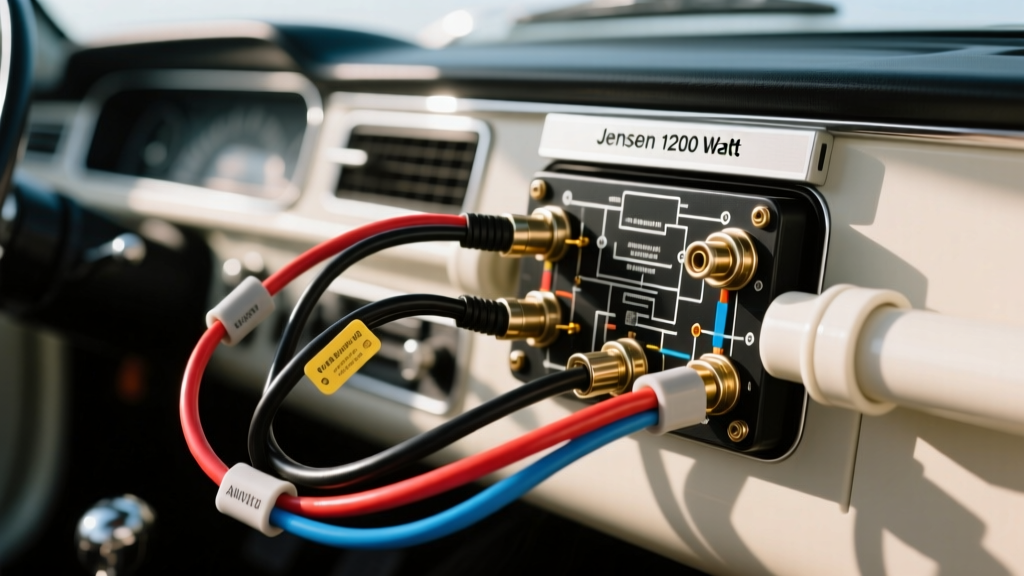
The High Stakes of a 1200-Watt Amplifier Installation
Installing a high-output amplifier like the Jensen 1200-watt Class D mono block is a transformative upgrade for any vehicle's audio system. However, pushing 1200 watts of RMS power into a subwoofer enclosure demands rigorous attention to electrical safety and wiring precision. A misinterpreted Jensen 1200 watt amp wiring diagram or a compromised ground connection will not just result in poor audio quality or clipping—it can lead to thermal runaway, melted insulation, or catastrophic vehicle fires. Modern Class D amplifiers operate at roughly 80% to 85% efficiency. To produce 1200 watts of audio output, the amplifier will draw approximately 1450 watts from your vehicle's electrical system. At a standard 14.4 volts (engine running), this equates to a continuous current draw exceeding 100 amps. This guide breaks down the most critical wiring mistakes, safety warnings, and diagnostic procedures to ensure your installation is both sonically impressive and electrically safe.
Decoding the Jensen 1200 Watt Amp Wiring Diagram
Before cutting a single zip tie or stripping wire, you must thoroughly understand the amplifier's terminal block layout. The standard Jensen 1200W wiring diagram features a high-current screw-terminal block for power and a separate section for signal inputs.
- B+ (Battery Positive): Accepts the main 12V power feed from the vehicle battery. This terminal requires a heavy-gauge wire and must be torqued securely to prevent arcing.
- GND (Chassis Ground): The return path for the electrical circuit. This must connect to bare, unpainted chassis metal within 18 inches of the amplifier.
- REM (Remote Turn-On): A low-current trigger wire (typically 18-16 AWG) that signals the amplifier's internal power supply to engage when the head unit turns on.
- RCA / High-Level Inputs: Signal inputs from the head unit or factory amplifier integration module.
Many installers rush through the diagram, confusing the REM terminal with a 12V constant power source, or mistakenly daisy-chaining multiple high-draw amplifiers to a single undersized power feed. Always reference the specific schematic provided in your Jensen manual, as terminal spacing and set-screw depths vary between model years.
Critical Mistake #1: Undersizing Power Wire and Using CCA
The most pervasive and dangerous mistake in mobile electronics is using Copper-Clad Aluminum (CCA) wire instead of Oxygen-Free Copper (OFC), and relying on generic 'wattage charts' rather than current-draw calculations. CCA wire has significantly higher electrical resistance than pure copper. When pushing 100+ amps through a 15-foot run of 4 AWG CCA wire, voltage drop and heat generation increase exponentially, often triggering the amplifier's thermal protection mode or melting the wire jacket.
According to the SAE J1128 Standard for low-tension primary automotive cable, wire gauge must be selected based on maximum amperage and total cable length (positive + ground). For a Jensen 1200W amp drawing ~105A, you must use true OFC wire.
| Wire Material | Recommended AWG (Up to 15ft Run) | Recommended AWG (15ft - 20ft Run) | Max Safe Amperage (14.4V) |
|---|---|---|---|
| Oxygen-Free Copper (OFC) | 4 AWG | 2 AWG | 125A - 150A |
| Copper-Clad Aluminum (CCA) | 2 AWG (Minimum) | 1/0 AWG | 90A - 110A |
Note: Always measure the total length of your power AND ground wire combined when calculating voltage drop. If your positive run is 12 feet and your ground is 3 feet, your total circuit length is 15 feet.
Critical Mistake #2: The Remote Turn-On (REM) Wire Voltage Drop
The REM terminal on your Jensen amplifier requires a minimum of 9V to 12V to engage the internal relay and power supply circuitry. A common mistake is tapping into the vehicle's power antenna wire or a shared accessory fuse that experiences severe voltage drop when multiple accessories (like HVAC blower motors or cooling fans) cycle on.
If the voltage at the REM terminal drops below the amplifier's threshold while the system is playing, the amp will rapidly cycle on and off, causing severe 'popping' transients that can destroy your subwoofer voice coils. Always use a dedicated 18 AWG primary wire run directly from the head unit's dedicated 'Blue/White' amplifier turn-on lead. If integrating with a factory audio system lacking a dedicated REM output, use a high-quality Digital Signal Processor (DSP) or a dedicated 12V trigger relay wired to an ignition-switched fuse in the cabin fuse box, ensuring the trigger circuit can supply at least 250mA.
Critical Mistake #3: High-Impedance Chassis Grounding Failures
Your amplifier's ground wire is not just a safety feature; it is the return half of your DC power circuit. A poor ground introduces high impedance, which restricts current flow, causes the amplifier's DC-DC converter to overwork, and generates massive amounts of heat. The Mobile Electronics Certification Program (MECP) strictly mandates that ground connections be made to bare, unpainted structural chassis metal.
The Proper Grounding Procedure:
- Locate a structural bolt or seatbelt anchor within 18 inches of the amplifier mounting location.
- Remove the bolt and use a wire brush or sandpaper to strip away all paint, powder coating, primer, and rust down to bright, bare steel.
- Apply a thin layer of dielectric grease over the bare metal after making the connection to prevent future oxidation and corrosion.
- Use a high-quality, tinned OFC ring terminal. Do not use indent crimpers; use a dedicated hex-crimp tool to ensure a gas-tight, cold-weld connection between the wire strands and the terminal barrel.
- Secure the terminal with a factory-grade flange nut or a Grade 8 bolt, torqued to the vehicle manufacturer's specification.
Safety Warnings: Fusing and Short Circuit Prevention
The primary fuse at the battery is not there to protect your amplifier; it is there to protect your vehicle from burning to the ground in the event of a short circuit between the battery and the amplifier. The Crutchfield Amplifier Installation Guide and all major insurance safety standards dictate that the main power fuse must be located within 18 inches of the vehicle's positive battery terminal.
For a 1200W Jensen amplifier utilizing 4 AWG or 2 AWG wire, you must use a high-quality ANL or Class-T fuse block. Avoid cheap glass AGU fuses for high-current applications, as the internal ferrule connections in cheap AGU holders can melt under continuous 100A loads. Furthermore, every single wire passing through a metal firewall or bulkhead must be protected by a rubber grommet. A vibrating chassis will slice through wire insulation in a matter of days, creating a direct short to ground that can ignite the vehicle if the main battery fuse fails or is incorrectly rated.
Troubleshooting Decision Tree: Protect Mode and No Power
If your Jensen 1200W amplifier fails to power on or immediately enters 'Protect' mode upon ignition, follow this systematic diagnostic tree using a Digital Multimeter (DMM):
- Symptom: Amp has no LED illumination.
- Step 1: Measure DC voltage between the B+ terminal and the vehicle chassis. (Expected: 12.4V engine off, 13.8V-14.4V engine on). If 0V, check main battery fuse and inline connections.
- Step 2: Measure DC voltage between the REM terminal and chassis. (Expected: 12V when head unit is on). If 0V, trace the remote wire back to the head unit.
- Step 3: Measure continuity between the GND terminal and the vehicle chassis. (Expected: near 0.0 ohms). If high resistance, rebuild the chassis ground point.
- Symptom: Amp powers on but immediately clicks into Protect Mode.
- Step 1: Disconnect all RCA inputs and Speaker Outputs. Turn the amp back on. If it stays on (Green/Blue LED), the fault is in your speaker wiring (shorted voice coil or pinched speaker wire) or a faulty RCA cable.
- Step 2: If it still enters Protect Mode with all outputs disconnected, measure the battery voltage at the B+ terminal while attempting to turn it on. If voltage drops below 10V instantly, the amplifier has an internal shorted output transistor or a failed DC-DC converter, requiring professional bench repair.
By respecting the physics of high-current DC electronics and strictly adhering to the Jensen 1200 watt amp wiring diagram, you ensure a reliable, safe, and thunderous audio experience for years to come.