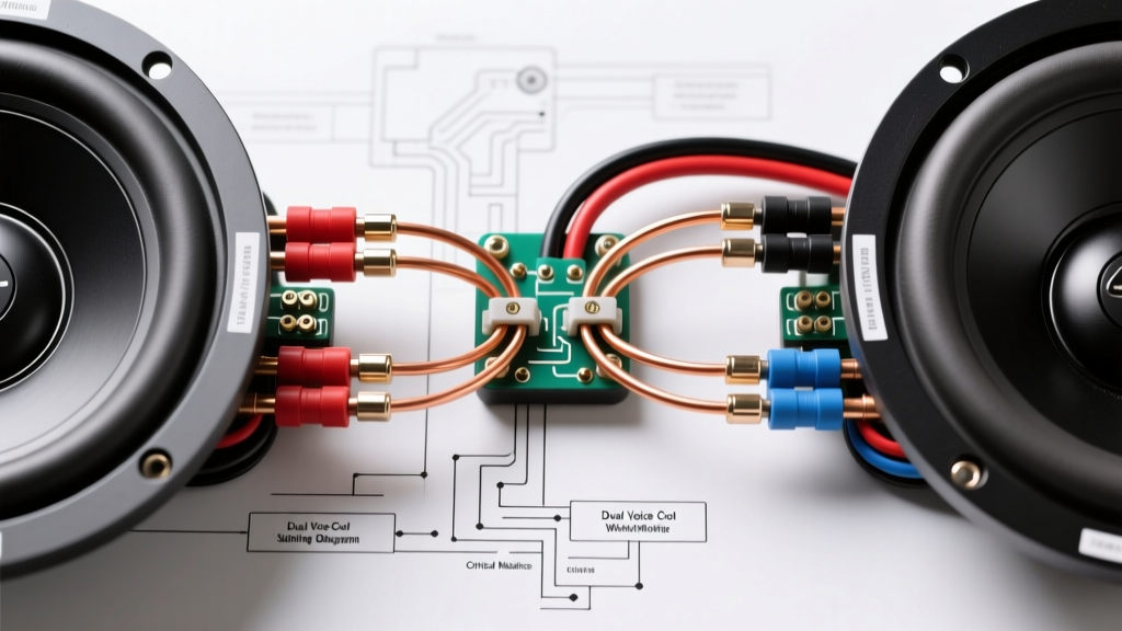
The Hidden Dangers in Your Dual Voice Coil Subwoofer Wiring Diagram
Upgrading your vehicle's low-end response requires more than just bolting a massive driver into the trunk. When working with a dual voice coil subwoofer wiring diagram, the margin for error shrinks significantly compared to single voice coil (SVC) setups. A dual voice coil (DVC) subwoofer features two separate windings wrapped around the same cylindrical former, terminating in four distinct connection points. This architecture provides immense flexibility for impedance matching, allowing you to wire the subwoofer in series, parallel, or series-parallel configurations to perfectly match your amplifier's optimal load.
However, this flexibility is a double-edged sword. Misinterpreting a wiring schematic, miscalculating the final Ohm load, or ignoring fundamental automotive electrical safety standards can result in catastrophic failure. From melted amplifier output transistors to severe acoustic cancellation, the consequences of a flawed installation are expensive and potentially dangerous. Below, we break down the most critical mistakes installers make when executing a DVC subwoofer wiring diagram and provide the exact protocols required to ensure a safe, high-fidelity installation.
The Impedance Mismatch Matrix: The Number One Amplifier Killer
The most frequent cause of amplifier failure in DVC installations is an impedance mismatch. Every amplifier is engineered to operate within a specific resistance window, typically measured in Ohms. Pushing an amplifier below its minimum stable impedance causes the power supply to overcurrent, triggering thermal protection or permanently damaging the output stage. Conversely, wiring the coils in series when parallel was intended will starve the amplifier of current, causing it to clip at lower volumes and send destructive square-wave DC voltage to the voice coils.
Refer to the matrix below to verify your target load before cutting a single wire. These calculations assume a single DVC subwoofer.
| Subwoofer Type | Wiring Configuration | Final Impedance (Ohms) | Typical Amplifier Compatibility |
|---|---|---|---|
| DVC 4-Ohm | Series | 8 Ohms | Standard 2/4-channel bridged (High efficiency, lower wattage) |
| DVC 4-Ohm | Parallel | 2 Ohms | Most modern Class D Mono-block amplifiers |
| DVC 2-Ohm | Series | 4 Ohms | Standard bridged 4-channel or older Class AB Mono amps |
| DVC 2-Ohm | Parallel | 1 Ohm | Specialized '1-Ohm Stable' Class D amplifiers only |
For a deeper understanding of how voice coil resistance fluctuates with temperature and frequency, consult the Crutchfield Subwoofer Impedance Guide, which details nominal vs. Re (DC resistance) specifications.
Five Fatal Wiring Mistakes and How to Avoid Them
1. Out-of-Phase Coil Wiring (Acoustic Cancellation)
When wiring the two coils of a DVC subwoofer in series or parallel, the polarity of the jumper wires must be perfectly aligned. If you wire Coil A positive-to-positive and Coil B positive-to-negative, the coils will fight each other electromagnetically. This results in severe acoustic cancellation, where the cone barely moves despite massive wattage being applied. The amplifier will read a near-zero impedance spike, often triggering immediate protection mode.
The Fix: Never rely solely on wire colors, as aftermarket speaker wire often lacks standardized automotive color codes. Instead, use the 9V battery trick. Briefly touch a 9V battery across the positive and negative terminals of a single coil. If the cone pushes outward, mark the terminal connected to the positive battery post with a red Sharpie. Repeat for the second coil. Always wire your jumpers from the verified positive terminal of Coil A to the verified negative terminal of Coil B for a series connection.
2. Undersized Power Wire and the CCA Trap
A common mistake when following a generic dual voice coil subwoofer wiring diagram is ignoring the amplifier's total current draw and using undersized or inferior power wire. Many budget wire kits use Copper-Clad Aluminum (CCA) instead of Oxygen-Free Copper (OFC). CCA has higher electrical resistance and lower thermal tolerance. According to SAE J1128 standards for low-tension primary cable, wire gauge must be calculated based on the maximum amperage draw and the total length of the run (positive plus ground).
The Fix: For a 1000W RMS Class D amplifier drawing roughly 85 amps at 14.4V, you must use a minimum of 4 AWG OFC wire for runs under 12 feet, and 1/0 AWG OFC for runs exceeding 16 feet. Always verify the wire is stamped with 'OFC' or 'AWG' specifications; avoid wires labeled only in 'gauge' without the AWG prefix, as they are often undersized CCA.
3. Chassis Grounding to Paint, Rust, or Sheet Metal Screws
The ground connection is the most critical point in your car audio electrical system. A poor ground introduces voltage drops, alternator whine, and clipping. Many installers simply drive a self-tapping sheet metal screw into a painted trunk floor. Paint and primer are insulators, and sheet metal screws do not provide adequate surface area or vibration resistance for high-current audio systems.
The Fix: Locate a structural chassis point (not a bolted-on bracket). Use a rotary tool with a sanding drum to strip away all paint, primer, and rust down to bare, shiny steel. Apply a thin layer of dielectric grease after tightening to prevent oxidation. Use a heavy-duty, heat-shrink insulated ring terminal crimped with a ratcheting crimper. Secure the ground using an M8 or M10 flange bolt with a star washer, torqued to 10-15 ft-lbs depending on the chassis steel thickness.
4. Bridging a Mono-Block Amplifier Incorrectly
Many modern Class D amplifiers designed for subwoofers are 'Mono-blocks', meaning they are internally bridged by design. They feature a single power supply optimized to drive a single low-impedance load. A frequent error occurs when an installer treats a mono-block like a standard 2-channel amplifier and attempts to 'bridge' the left and right speaker terminals, or wires two DVC subwoofers in parallel to a mono amp that is only stable down to 2 Ohms, dropping the final load to a dangerous 0.5 Ohms.
The Fix: Always read the amplifier's manual. On a mono-block, the positive and negative terminals for the left and right channels are usually internally tied together. You simply distribute the speaker wires across the available terminals to secure the thick 12 AWG OFC speaker wire properly. Never wire a mono amp's L+ to an R- terminal unless the manufacturer's schematic explicitly dictates it for a specific high-power strapping configuration.
5. Skipping the Main Power Fuse or Misplacing It
The fuse on your amplifier's chassis protects the amplifier's internal circuitry; it does not protect your vehicle from a catastrophic electrical fire. If the uninsulated main power wire rubs against a sharp metal edge near the firewall, it will short directly to the battery, melting the wire harness and potentially igniting the vehicle's interior within seconds.
The Fix: You must install an ANL or AGU main power fuse within 18 inches of the positive battery terminal. For a 1/0 AWG wire feeding a 150A system, use a 150A or 200A ANL fuse housed in a sealed, waterproof distribution block. Avoid cheap glass AGU fuses for high-current applications, as the internal element can arc and fail to break the circuit during a massive dead-short.
Pre-Flight Safety Checklist: Multimeter Testing
Before connecting the RCA cables or applying 12V power to the amplifier's remote turn-on terminal, you must verify the physical wiring with a digital multimeter (DMM). This 5-minute step saves thousands of dollars in blown equipment.
- Step 1: Verify Open Circuits. Set your DMM to continuity mode. Touch one probe to the bare positive speaker wire at the amplifier end, and the other probe to the vehicle's chassis ground. There should be zero continuity (infinite resistance). If it beeps, you have a pinched wire shorting to the chassis.
- Step 2: Measure Final DC Resistance (Re). Set the DMM to the 200 Ohm scale. Measure the resistance directly across the speaker terminals at the amplifier. If you wired two DVC 4-Ohm subwoofers in parallel for a 1-Ohm load, your multimeter should read approximately 0.8 to 1.2 Ohms (accounting for the resistance of the 12 AWG speaker wire). If it reads 4 Ohms, your parallel jumper wires are incorrect.
- Step 3: Check Power and Ground Voltage Drop. Turn the vehicle on and play a 50Hz test tone at a moderate volume. Measure DC voltage directly at the amplifier's positive and ground set-screws. If the voltage drops below 12.5V under load, your power wire is undersized, your ground is poor, or your vehicle's alternator cannot keep up with the current demand.
By strictly adhering to these protocols and treating the dual voice coil subwoofer wiring diagram as a precise electrical blueprint rather than a suggestion, you ensure maximum output, thermal reliability, and long-term safety for your vehicle's audio system. For professional certification standards on mobile electronics installation, refer to the guidelines established by the Mobile Electronics Certification Program (MECP).