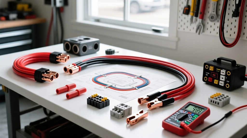
Deconstructing the 50 Amp Wiring Diagram
When installing a mid-tier monoblock subwoofer amplifier (e.g., 500W to 800W RMS) or a high-power 4-channel component amp, a 50-amp circuit is the standard electrical requirement. Before purchasing materials, it is critical to understand the exact nodes of a 50 amp wiring diagram to accurately forecast costs and select the proper installation tools. A standard 50A car audio power circuit consists of the following pathway: Battery Positive Terminal → 50A ANL Fuse (within 18 inches of the battery) → Firewall Grommet → Cabin Routing → Amplifier +12V Terminal. The ground circuit completes the loop from the Amplifier GND terminal to a bare-metal chassis point within 3 feet of the amp.
While the diagram itself is simple, the execution dictates the longevity and safety of your vehicle's electrical system. A 50A continuous draw at 14.4V equates to 720 watts of electrical power. Any high-resistance connection in this pathway will generate excessive heat, leading to voltage drop, clipped audio signals, or in worst-case scenarios, an electrical fire. This guide breaks down the exact material costs and tool requirements to execute this diagram flawlessly.
Material Cost Analysis: OFC vs. CCA Wire
The most significant variable in your budget will be the power and ground wire. For a 50A circuit, the SAE J1128 standard and standard AWG charts recommend 8 AWG wire for runs under 10 feet. However, automotive electrical experts universally recommend stepping up to 4 AWG wire for 50A circuits to minimize voltage drop, accommodate future amplifier upgrades, and compensate for the high operating temperatures inside a vehicle cabin.
The market is divided between Oxygen-Free Copper (OFC) and Copper-Clad Aluminum (CCA). CCA wire is significantly cheaper but possesses higher electrical resistance. Furthermore, many budget CCA wires use SAE sizing rather than true AWG, meaning a "4 AWG" CCA wire may actually be as thin as a 6 AWG OFC wire, dangerously undersizing your 50A circuit.
| Component | Specification | CCA Budget Cost | OFC Premium Cost |
|---|---|---|---|
| Power Wire (15 ft) | 4 AWG Red | $25.00 | $65.00 |
| Ground Wire (3 ft) | 4 AWG Black | $5.00 | $15.00 |
| Main Fuse & Holder | 50A ANL (Not AGU) | $15.00 | $15.00 |
| Ring Terminals (4 pk) | Tinned Copper, 5/16" stud | $12.00 | $12.00 |
| Heat Shrink Tubing | 3:1 Adhesive-Lined Marine | $8.00 | $8.00 |
| Distribution Block | Nickel-Plated Brass (1 in / 2 out) | $18.00 | $22.00 |
| Total Estimated Cost | $83.00 | $137.00 |
Note: Never use AGU glass fuses for a 50A circuit. AGU fuses have high internal resistance and the glass housing can melt or shatter under sustained high-current loads. Always use an ANL or MINI-ANL bolt-down fuse.
Essential Tool Requirements & Budgeting
Executing a 50 amp wiring diagram requires more than a pair of wire cutters. High-current circuits demand low-resistance terminations. If a 4 AWG terminal is poorly crimped, the micro-gaps between the wire strands and the terminal barrel will act as a resistor, generating heat and dropping voltage before it ever reaches the amplifier's capacitors.
The Professional's Tool Checklist
- Hex-Crimp Tool (4 AWG to 1/0 AWG): ($40 - $80) Avoid cheap ratcheting crimpers that simply smash the terminal flat. A proper hex-crimp tool compresses the terminal into a tight, symmetrical hexagon, ensuring maximum surface area contact and pulling the wire deep into the barrel.
- Digital Multimeter (True RMS): ($30 - $50) Essential for verifying alternator output, checking for voltage drop across the fuse, and ensuring the remote turn-on wire is receiving a clean 12V signal.
- Heavy-Duty Wire Strippers: ($25 - $40) Stripping 4 AWG wire with a utility knife often nicks the outer copper strands, creating a weak point that will snap under vibration. Use dedicated heavy-gauge strippers or the careful scoring-and-twisting method.
- Heat Gun: ($20 - $30) Do not use a cigarette lighter to shrink marine heat shrink. A lighter creates uneven heat, causing the adhesive to fail and allowing moisture to corrode the tinned copper terminals.
- Rotary Tool or Sandpaper (80-grit): ($15) Required for removing paint, clear coat, and rust from the chassis grounding point.
Step-by-Step Tool Application for the 50A Circuit
According to installation guidelines outlined by Crutchfield's master technicians, the sequence of termination and grounding is where most DIY installers introduce resistance into the system. Follow this tool-application sequence to ensure your 50A diagram performs flawlessly.
1. Terminal Crimping and Sealing
Strip exactly 3/4" of insulation from the 4 AWG wire. Slide a piece of 3:1 adhesive-lined heat shrink onto the wire before inserting the wire into the tinned copper ring terminal. Insert the wire until it bottoms out in the barrel. Use your hex-crimp tool to compress the terminal. You should see a small amount of copper strand protruding from the front of the terminal barrel—this confirms the wire was fully seated. Apply heat evenly with the heat gun until the adhesive oozes out of both ends of the shrink tube, creating a watertight seal.
2. The Chassis Ground Preparation
The ground connection is responsible for carrying the full 50A return current back to the battery's negative terminal via the chassis. Locate a thick, structural piece of the vehicle's frame or floor pan within 3 feet of the amplifier. Use your rotary tool with a sanding drum or 80-grit sandpaper to remove all paint, primer, and undercoating down to bare, shiny steel.
Attach the 4 AWG ground ring terminal using an M8 or M10 stainless steel bolt, a star washer (to bite into the bare metal), and a nylon-insert lock nut. Torque the bolt to 10-15 Nm. Immediately coat the exposed bare metal and terminal with dielectric grease or a spray-on battery terminal protector to prevent flash rust, which will rapidly increase ground resistance.
Hidden Costs & Failure Mode Prevention
When budgeting for a 50 amp wiring diagram, many enthusiasts forget to account for the strain placed on the vehicle's factory charging system. A 50A draw at idle (when the alternator is spinning slowly and producing minimal amperage) can easily exceed the alternator's surplus capacity, forcing the amplifier to pull current from the battery. This results in dimming headlights, clipped bass notes, and premature alternator failure.
Voltage Drop Testing
Once the system is wired and playing music at moderate volume, use your multimeter to perform a voltage drop test. Set the multimeter to DC Volts. Place the red probe on the amplifier's +12V terminal and the black probe on the amplifier's ground terminal. Under heavy load, the voltage should not drop below 12.5V.
If you measure a significant drop, move the black probe to the battery's negative terminal. If the voltage reading increases, your chassis ground is inadequate (clean it again or run a dedicated 4 AWG ground wire directly to the battery). If the voltage remains low, the issue is on the power side—check your hex crimps and ensure your 50A ANL fuse holder contacts are tight and free of oxidation.
The "Big 3" Upgrade Consideration
If your vehicle features a low-output factory alternator (e.g., 80A to 100A), adding a 50A car audio circuit will consume over 50% of its total capacity. To prevent voltage drop and protect your factory wiring harness, budget an additional $60 to $90 for a "Big 3" wiring upgrade kit. This involves replacing the alternator positive, engine block ground, and chassis ground wires with 1/0 AWG OFC wire, drastically lowering the resistance of the vehicle's core electrical loop and ensuring your 50A amplifier receives clean, uninterrupted current.