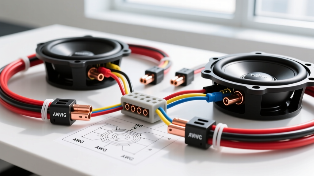
Project Scope: Upgrading to a Dual DVC 4-Ohm Configuration
Upgrading from a factory audio system or a basic single-subwoofer setup to a high-output dual subwoofer configuration requires meticulous impedance management and robust power delivery. When executing an upgrade project utilizing Dual Voice Coil (DVC) 4-ohm subwoofers, the primary objective is typically to wire the voice coils to a final 1-ohm load. This specific impedance target allows you to extract the maximum rated RMS wattage from a high-current, 1-ohm stable Class D monoblock amplifier. However, pushing an amplifier to its absolute minimum impedance threshold generates significant thermal mass and demands flawless wiring execution. A poorly executed subwoofer wiring diagram will result in severe voltage drop, thermal compression, and immediate activation of the amplifier's protection circuitry.
This comprehensive upgrade guide details the exact topology, wire gauge requirements, and termination procedures necessary to safely wire two DVC 4-ohm subwoofers to a 1-ohm final load. We will cover the all-parallel wiring schematic, the mandatory 'Big Three' power infrastructure upgrades, and pre-flight validation using a digital multimeter (DMM).
Impedance Mathematics: Achieving a 1-Ohm Final Load
Before cutting any wire, it is critical to understand the mathematical relationship between the individual voice coils and the final load presented to the amplifier. A DVC 4-ohm subwoofer features two independent 4-ohm voice coils per driver. With two subwoofers in your enclosure, you are working with a total of four 4-ohm coils.
- Series Wiring: Adds impedance. Wiring two 4-ohm coils in series yields 8 ohms.
- Parallel Wiring: Divides impedance. Wiring two 4-ohm coils in parallel yields 2 ohms.
To achieve a 1-ohm final load from four 4-ohm coils, you must wire every single voice coil in parallel. The formula for parallel resistance is 1 / (1/R1 + 1/R2 + 1/R3 + 1/R4). Applying our values: 1 / (1/4 + 1/4 + 1/4 + 1/4) = 1 / (4/4) = 1 ohm. This all-parallel topology is the only safe and mathematically sound method to reach 1 ohm with this specific driver configuration.
Dual 4-Ohm Subwoofer Wiring Diagram: All-Parallel Topology
The following schematic outlines the physical routing of the speaker wire. For a 1-ohm load pushing upwards of 1500W RMS, you must use a minimum of 8 AWG Oxygen-Free Copper (OFC) speaker wire. Do not use Copper Clad Aluminum (CCA), as its higher resistance will cause signal degradation and heat buildup at the amplifier terminals.
Subwoofer 1 Termination
- Identify Voice Coil 1 (VC1) and Voice Coil 2 (VC2) on Subwoofer 1.
- Install a short jumper wire from the positive terminal of VC1 to the positive terminal of VC2.
- Install a second jumper wire from the negative terminal of VC1 to the negative terminal of VC2.
- Connect your main 8 AWG positive speaker run to the positive terminal of VC1.
- Connect your main 8 AWG negative speaker run to the negative terminal of VC1.
Subwoofer 2 Termination
- Repeat the exact jumper process for Voice Coil 3 (VC3) and Voice Coil 4 (VC4) on Subwoofer 2.
- Connect the second main 8 AWG positive and negative speaker runs to VC3.
Amplifier Termination
Because most monoblock amplifiers do not have physical terminal blocks large enough to accept four 8 AWG wires simultaneously, you must use a speaker wire distribution block or carefully stack and crimp the wires using a closed-end nylon-insulated crimp connector before inserting them into the amplifier's set-screw terminals. The amplifier's positive terminal feeds both Subwoofer 1 and Subwoofer 2 positive leads, and the negative terminal feeds both negative leads.
Power, Ground, and the 'Big Three' Infrastructure
Drawing 1500+ watts at 1 ohm requires roughly 125 to 150 amps of continuous current from your vehicle's electrical system. Standard factory wiring cannot sustain this draw without experiencing catastrophic voltage drop. According to the SAE International J1128 Standard for low-tension primary cables, automotive wiring must be rated for specific thermal limits; factory 10 AWG alternator wires will melt under sustained 150A loads.
Before running your main amplifier power wire, you must perform the 'Big Three' upgrade. This involves replacing or supplementing the following factory wires with 1/0 AWG OFC:
- Alternator positive to Battery positive.
- Battery negative to Vehicle Chassis.
- Engine block to Vehicle Chassis.
AWG Specification Chart for High-Current Monoblocks
| Total RMS Wattage | Max Current Draw | Recommended Wire Gauge (OFC) | Main Fuse Rating (ANL) |
|---|---|---|---|
| 500W - 800W | ~70 Amps | 4 AWG | 80A |
| 800W - 1200W | ~110 Amps | 1/0 AWG | 120A |
| 1200W - 1800W | ~160 Amps | 1/0 AWG or 2/0 AWG | 175A |
| 1800W - 2500W+ | 200+ Amps | 2/0 AWG | 225A+ |
Note: Always install the main ANL or Class-T fuse within 18 inches of the positive battery terminal to protect the vehicle from catastrophic short circuits, as mandated by mobile electronics safety standards.
Signal Integrity: RCA Routing and Remote Turn-On
High-gain monoblock amplifiers are notoriously susceptible to electromagnetic interference (EMI) and alternator whine. When routing your RCA signal cables, they must travel down the opposite side of the vehicle's cabin from the 1/0 AWG power wire. If crossing the power wire is unavoidable, do so at a strict 90-degree angle to minimize inductive coupling.
For the remote turn-on wire, use 18 AWG primary wire (typically blue with a white stripe). Connect this to the head unit's remote output or a fuse tap on an ignition-switched accessory circuit. If your amplifier features a high-current cooling fan or you are daisy-chaining multiple amplifiers, the head unit's remote lead may not supply enough current (often limited to 150mA). In this scenario, wire a 30A automotive relay triggered by the head unit, pulling the main remote switching current directly from the fused 12V accessory line.
Pre-Flight Validation: Testing with a Digital Multimeter
Never power on a 1-ohm configured amplifier without first verifying the impedance with a Digital Multimeter (DMM). Set your DMM to the Ohms (Ω) setting and place the probes across the amplifier's positive and negative speaker terminals.
Crucial Technical Note: You will not read exactly 1.0 ohms. A multimeter measures DC Resistance (Re), not AC Impedance (Z). A nominal 1-ohm load will typically read between 0.75Ω and 0.85Ω on a DMM. If your meter reads 'OL' (Open Loop), you have a broken jumper or loose crimp. If it reads '0.00' or near zero, you have a dead short (positive and negative touching) and must immediately re-inspect your terminal crimps before applying power.
Once impedance is verified, power the system on and use a DMM to measure the DC voltage directly at the amplifier's B+ and Ground terminals while playing a 40Hz sine wave at moderate volume. If the voltage drops below 11.5V, your charging system or ground termination is failing, and you must revisit your chassis grounding point. Ensure the ground ring terminal is crimped using a hex-crimp tool and bolted to bare, unpainted steel using an M8 or M10 bolt torqued to factory chassis specifications.
Authoritative References
- SAE International J1128 Standard - Low Tension Primary Cable specifications for automotive environments.
- Crutchfield Car Audio Wiring Guide - Industry-standard installation practices and wire routing methodologies.
- JL Audio Amplifier Technical Documentation - CEA-2006 compliance and 1-ohm thermal stability testing parameters.