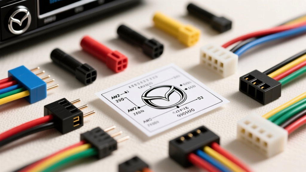
Understanding Mazda Radio Wiring Diagram Color Codes
Upgrading the factory head unit in a Mazda vehicle requires a precise understanding of the OEM wiring architecture. Unlike older domestic vehicles that relied on simple 12V switched lines, modern Mazdas (particularly 2006 and newer) utilize CAN-bus data networks, Retained Accessory Power (RAP), and proprietary Bose amplifier integration. When consulting a color codes Mazda radio wiring diagram, selecting the correct aftermarket harness adapter is critical to prevent data bus conflicts, battery drain, or blown amplifier channels.
This selection guide compares the most reliable aftermarket wiring interfaces against factory Mazda pinouts, helping you choose the exact harness for your specific model year, trim level, and audio configuration.
Standard Mazda 16-Pin vs. 22-Pin Bose Connector Pinouts
Mazda primarily utilizes two main chassis connectors behind the radio: the standard 16-pin block for base audio systems, and the 22-pin (or dual-plug) configuration for Bose amplified systems. Below is the foundational color code reference for the standard 16-pin non-amplified harness, which serves as the baseline for most aftermarket harness selections.
| Pin | Function | Factory Wire Color | Aftermarket Equivalent |
|---|---|---|---|
| 1 | Constant 12V (B+) | Blue/Red or Blue/Yellow | Yellow |
| 2 | Switched 12V (ACC) | Blue/White or Blue/Black | Red |
| 3 | Ground | Black | Black |
| 4 | Illumination | Red/Black | Orange/White |
| 5 | Front Left (+) | White | White |
| 6 | Front Left (-) | White/Black | White/Black |
| 7 | Front Right (+) | Red | Gray |
| 8 | Front Right (-) | Red/Black | Gray/Black |
| 14 | CAN-H (Data) | White/Red | N/A (Requires Interface) |
| 15 | CAN-L (Data) | White/Blue | N/A (Requires Interface) |
Note: Speaker wire colors for rear channels (Green/Green-Black and Purple/Purple-Black) are present on pins 9-12 in non-Bose models. In Bose-equipped models, these pins are either empty or carry low-level pre-amp signals to the factory amplifier.
Product Comparison: Selecting the Right Mazda Wiring Harness
Choosing the wrong harness for a Mazda can result in the radio failing to turn off (parasitic draw) or the loss of steering wheel audio controls. Based on factory wiring diagrams, here is how the top three aftermarket harness solutions compare.
1. Metra 70-1771 (Standard Non-Amplified)
Best For: Base model Mazda 3, Mazda 5, and CX-5 (without Bose or premium audio).
Technical Profile: This is a basic plug-and-play adapter that maps the Mazda 16-pin chassis plug to a standard 1988+ aftermarket radio harness. It handles standard 12V B+, ACC, Ground, and 4-channel speaker outputs.
Limitation: It does not decode CAN-bus data. If your Mazda uses data-switched ACC (where Pin 2 does not provide true 12V ignition, but relies on the CAN-bus sleep/wake signal), this harness will require tapping the ignition switch cylinder or OBDII port for a switched 12V source.
2. Axxess AX-MZ611 (Bose Amplified Integration)
Best For: Mazda vehicles equipped with the factory Bose amplifier (e.g., Mazda 6 Grand Touring, CX-9 with Bose).
Technical Profile: The Bose system uses high-level amplified signals sent through the 22-pin connector. The AX-MZ611 features a built-in line output converter (LOC) that steps down the high-level Bose speaker outputs to low-level RCA signals.
Wiring Note: When using this harness, you must bypass the factory Bose amplifier's power circuit. According to Mazda3 Forums technical archives, you must supply 12V constant and switched power directly to the factory amp's B+ and ACC pins (typically Blue/Red and Blue/White) via the harness's blue/white remote turn-on wire to wake the amp up.
3. PAC RP4-MZ11 (CAN-Bus Data & Steering Wheel Interface)
Best For: 2014+ Mazda 3, Mazda 6, and CX-5 with MZD Connect or data-switched ignition systems.
Technical Profile: This is a comprehensive data interface. It reads the CAN-H and CAN-L signals (Pins 14 and 15) to generate a standard 12V ACC output, eliminating the need to splice into the ignition switch. It also retains RAP, chimes, and factory steering wheel controls (SWC).
Selection Rule: If your wiring diagram shows CAN-bus wires on the radio plug and no dedicated 12V ACC wire, the PAC RP4-MZ11 or Axxess AXTO-MZ is mandatory.
Wire Gauge Specifications and Termination Standards
When splicing an aftermarket harness to a Mazda factory plug, adhering to SAE J1128 wiring standards is critical for fire safety and signal integrity. Do not use cheap T-tap scotch locks, which oxidize and fail under the vibration of a dashboard environment.
- Main Power (B+) & Ground: Use minimum 12 AWG primary wire. Mazda's factory B+ wire is often 14 AWG, but upgrading to 12 AWG reduces voltage drop for high-draw aftermarket head units with internal amplifiers.
- Speaker Wires: Use 18 AWG stranded copper. For Bose bypass applications where you are running new speaker wires from the head unit directly to the doors, upgrade to 16 AWG to compensate for the longer run through the door jam rubber boots.
- Data / CAN-Bus Wires: 22 AWG twisted pair is sufficient. Keep CAN-H and CAN-L away from high-current power wires to prevent electromagnetic interference (EMI) which can cause network faults on the Mazda MS-CAN bus.
- Termination: Use Posi-Twist connectors or, ideally, solder joints sealed with adhesive-lined dual-wall heat shrink tubing. This prevents moisture ingress, a common failure point in Mazda hatchbacks where trunk humidity can travel up the wiring loom.
Troubleshooting Common Mazda Stereo Wiring Issues
Even with the correct color codes Mazda radio wiring diagram, integration issues can arise. Use this decision matrix to diagnose post-installation faults.
| Symptom | Probable Cause | Technical Fix |
|---|---|---|
| Radio stays on after key removal / Battery drains overnight. | Head unit is wired to Constant 12V instead of Switched 12V, or CAN-bus sleep mode is being interrupted. | Verify Pin 1 (Blue/Red) and Pin 2 (Blue/White) with a multimeter. If using a data module, ensure the module firmware is updated to recognize the specific Mazda sleep-cycle protocol. |
| Audio plays only from front dash tweeters (No door speakers). | Factory Bose amplifier is not turning on, or rear speaker pins are misidentified on the 22-pin plug. | Check the amp turn-on circuit. The factory amp requires both 12V B+ and a 12V ACC signal to engage the internal relays. Supply 12V ACC via the head unit's Blue/White remote wire. |
| Alternator whine in the audio signal that increases with RPM. | Ground loop created by grounding the aftermarket radio to a painted chassis bolt or sharing a ground with the data module. | Route a dedicated 12 AWG ground wire to a clean, unpainted metal bracket behind the dash, or utilize the factory radio ground point (Pin 3, Black wire) using a high-quality crimp terminal. |
| Steering wheel volume buttons do not respond. | Resistance-based SWC wires not connected to the aftermarket radio's SWC input, or CAN-bus module not programmed. | For older resistance-based Mazdas, connect the Key-A and Key-B wires to the radio. For CAN-bus Mazdas, use the PAC RP4-MZ11 and follow the 12-step button programming sequence outlined in the Crutchfield SWC integration guide. |
Final Selection Advice
Never rely solely on wire color when modifying a Mazda audio system. Factory harness revisions occur mid-year, and a 2012 Mazda 3 might have a different pinout than a 2013 Mazda 3 built in the same plant. Always verify the pin functions with a digital multimeter against a vehicle-specific factory service manual diagram before applying power. Investing in a high-quality CAN-bus interface like the PAC RP4-MZ11 will save hours of diagnostic time and protect your vehicle's delicate MS-CAN network from backfeeding voltage.