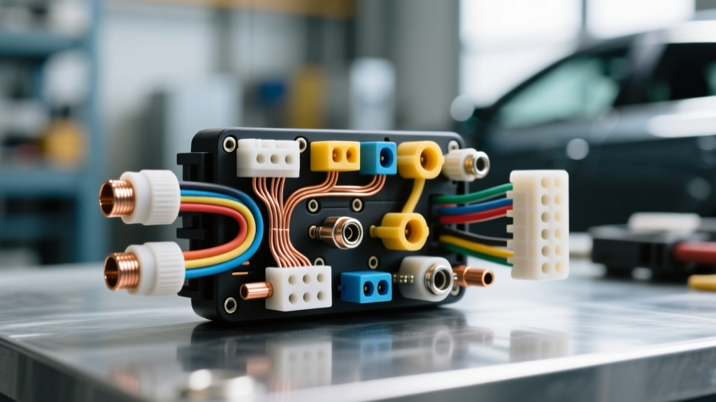
Introduction to Connector-Level Diagnostics
When diagnosing automotive electrical faults, especially during complex engine swaps or OEM harness restorations, the root cause is rarely the wire itself. According to industry failure analysis data, over 70% of harness-related electrical gremlins originate at the connection point. Understanding the specific engineering and failure modes of different wiring harness connector types is mandatory for any serious automotive electrician. Whether you are troubleshooting a flickering instrument cluster on a 2004 Silverado or diagnosing a CAN bus communication failure on an LS-swapped Nissan 240SX, applying a structured, step-by-step troubleshooting flow will save you hours of chasing phantom voltage drops.
This guide provides a master-level diagnostic flow for identifying, testing, and repairing the most common sealed and unsealed automotive connectors, including Delphi/Aptiv Metri-Pack, Weather-Pack, TE Connectivity Superseal, and Deutsch DT series.
Phase 1: Visual Identification and Mechanical Inspection
Before reaching for a digital multimeter (DMM), you must correctly identify the connector family. Misidentifying a connector type often leads to using the wrong extraction tool, which destroys the terminal locking tang and ruins the connector housing.
Step 1: Identify the Connector Family and Series
- Metri-Pack 150 Series: Features a 0.64mm male blade width. Typically handles 18 to 22 AWG wire. Common in low-current sensor circuits (e.g., coolant temperature sensors, TPS). Look for the small, stamped locking tang on the side of the female terminal.
- Metri-Pack 280 Series: Features a 2.8mm male blade width. Handles 14 to 16 AWG wire. Used for high-current circuits like fuel injectors, ignition coils, and blower motors.
- Weather-Pack: Distinguished by its bulky, rounded housings and individual wire seals that slide over the insulation. Handles 10 to 14 AWG wire. Terminals lock into the housing via a flexible barb mechanism.
- TE Superseal 1.5: Common in European and late-model domestic applications. Features a secondary locking wedge (often yellow or red) that slides into the front of the housing to prevent terminal back-out.
Step 2: Inspect Locking Mechanisms (CPA and TPA)
Modern harnesses utilize two critical locking features that frequently fail if improperly seated during previous repairs:
- TPA (Terminal Position Assurance): A plastic comb inserted into the rear of the connector. If the terminal is not fully seated, the TPA will not click into place. Diagnostic Action: If the TPA is sitting proud (not flush), you have a partially backed-out terminal causing intermittent resistance.
- CPA (Connector Position Assurance): A secondary lock (often red or yellow) on the exterior of the mated halves. It prevents the primary latch from vibrating loose. Diagnostic Action: Never force a CPA lock in before the primary latch has fully engaged and clicked.
Phase 2: Electrical Testing and Voltage Drop Analysis
Once the mechanical integrity is verified, proceed to electrical testing. Continuity testing (measuring resistance with the circuit off) is insufficient for diagnosing high-resistance faults under load. You must perform a live voltage drop test.
Step 3: Perform a Live Voltage Drop Test
Set your DMM to DC Volts. Back-probe the connector while the circuit is active and under load.
- Acceptable Drop: Less than 0.1V for low-current signal circuits (e.g., 5V reference to a MAP sensor). Less than 0.2V for high-current power circuits (e.g., headlight power feed).
- Critical Fault: A drop greater than 0.5V across a single mated connector pair indicates severe internal resistance, usually caused by fretting corrosion or a compromised crimp.
Step 4: CAN Bus Specific Diagnostics (OBD-II Port)
If you are troubleshooting a network communication fault, you will likely be working with the Data Link Connector (DLC). The standard OBD-II port utilizes a sealed Metri-Pack 280 style housing.
- Pin 6 (CAN High): Typically Dark Green or White. Idle voltage ~2.6V.
- Pin 14 (CAN Low): Typically Dark Blue or Purple. Idle voltage ~2.4V.
- Diagnostic Action: Measure the resistance between Pin 6 and Pin 14 with the battery disconnected. You must read exactly 60 ohms (two 120-ohm termination resistors in parallel). If you read 120 ohms, one of the network terminator modules or harness connectors is open.
Phase 3: Troubleshooting Decision Matrix
Use the following matrix to quickly isolate the failure mode based on your physical and electrical findings.
| Symptom / Observation | Likely Connector Type Suspect | Root Cause Analysis | Corrective Action |
|---|---|---|---|
| Green/white crust on pins | Unsealed Metri-Pack or Weather-Pack | Galvanic corrosion due to moisture ingress and dissimilar metals. | Clean with electrical contact cleaner. Apply Nyogel 760G dielectric grease. Replace if pitted. |
| Intermittent signal loss over bumps | TE Superseal or Metri-Pack 150 | Fretting corrosion or missing TPA lock allowing micro-movements. | Verify TPA seating. Replace female terminal if the internal beryllium-copper spring has lost tension. |
| Melted plastic housing | Metri-Pack 280 (High Current) | Excessive resistance generating heat, often from a poor barrel crimp on 12-14 AWG wire. | Cut back wire. Perform a new crimp using a Delphi-approved ratcheting crimper. Verify pull-force. |
| High resistance on 5V Ref circuit | Weather-Pack (Sensor side) | Over-application of standard silicone grease blocking low-current signal transfer. | Remove standard grease. Use only carbon-impregnated or specialized automotive dielectric compounds. |
Phase 4: Terminal Extraction and Proper Repair Protocols
When a terminal is damaged, it must be extracted and replaced. Forcing a terminal out will snap the internal housing barbs, rendering the entire connector shell useless.
Step 5: Select the Correct Extraction Tool
- Weather-Pack Terminals: These lock via a folded barb. You must use a hollow, tube-style extraction tool that slides over the wire, depressing the barbs inward while you pull from the rear.
- Metri-Pack Terminals: These lock via a stamped tang on the side. You must use a flat, blade-style tool (like the Delphi 12094429 equivalent) to slide alongside the terminal, depressing the tang away from the housing wall.
Step 6: Execute the Correct Crimp Specification
Automotive terminals require specific crimp profiles. A standard electrical plier crimp will fail under engine bay vibration.
- Weather-Pack (Double Crimp): The terminal has two crimp wings. The front wings must crush the bare wire strands (conductor crimp), while the rear wings must tightly wrap the wire insulation (support crimp). This prevents the wire from pulling out under tension. Target pull-force for 14 AWG is a minimum of 30 lbs.
- Metri-Pack (Single Crimp): Features only a conductor crimp. The wire seal is loaded separately onto the wire before crimping. Ensure the wire strands are visible just past the front of the crimp barrel (approx. 1mm) to guarantee full insertion depth.
Advanced Environmental Sealing: The Dielectric Grease Debate
A common mistake in harness repair is the misuse of dielectric grease. Standard silicone grease is an insulator. If applied directly to the mating faces of low-current signal pins (like a 5V reference or CAN bus line), it can increase contact resistance and trigger a PCM fault code. For sealed wiring harness connector types, the industry standard is Nyogel 760G or an equivalent carbon-impregnated synthetic grease. This compound lubricates the rubber weather seals to prevent tearing during insertion, displaces moisture, and maintains conductivity across the metal-to-metal contact points of the terminals. Always apply the grease to the seals and the rear of the terminal, not directly packed into the pin socket.
Summary and Authoritative References
Mastering the troubleshooting flow for wiring harness connector types transitions you from a parts-swapper to a true automotive electrical diagnostician. By respecting the mechanical locking designs, utilizing live voltage drop testing, and adhering to OEM crimp specifications, you ensure long-term reliability for both OEM restorations and custom aftermarket harnesses.
For further technical specifications and engineering standards referenced in this guide, consult the following authoritative resources:
- Aptiv (formerly Delphi) Connection Systems Engineering Catalog - Detailed specifications for Metri-Pack and Weather-Pack terminal pull-forces and crimp profiles.
- SAE International Standard J1128 - Guidelines for low-tension primary cable and wire insulation requirements in automotive harnesses.
- TE Connectivity Automotive Superseal 1.5 Series Datasheet - Mating force data and environmental sealing test results for TE harness connectors.