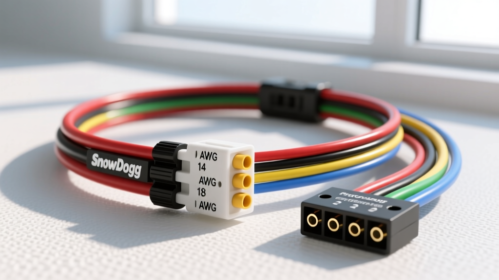
Introduction to SnowDogg Plow Electrical Systems
Upgrading your truck with a commercial snow plow is a major investment, and the electrical system is the nervous system that makes it all work. For beginners, looking at a SnowDogg wiring harness diagram for the first time can feel like deciphering an alien language. However, once you understand the fundamental building blocks of automotive electrical schematics, these diagrams become powerful troubleshooting and installation tools.
SnowDogg, manufactured by Buyers Products, utilizes robust multiplex electrical systems and heavy-duty solenoid-driven hydraulic circuits. Unlike simple trailer wiring, a plow harness must handle massive current spikes to power the hydraulic pump motor, while simultaneously managing delicate CAN-bus or multiplex signals for the in-cab controller. This guide breaks down the core elements of SnowDogg wiring diagrams, translating complex schematics into beginner-friendly fundamentals.
How to Read a SnowDogg Wiring Harness Diagram
Before cutting, crimping, or routing any wires, you must understand the visual language of the schematic. SnowDogg diagrams generally follow standard automotive electrical conventions, heavily influenced by SAE J1128 standards for low-tension primary cables.
Key Schematic Symbols
- Battery/Power Source: Represented by a series of parallel lines (one long, one short) or a simple battery icon. In SnowDogg diagrams, this is often labeled 'B+' or 'BAT'.
- Ground (Earth): Depicted as three descending horizontal lines or a simple line pointing to the chassis. A poor ground is the number one cause of plow electrical failure.
- Relays and Solenoids: Shown as a square (the coil) connected to a switch symbol. SnowDogg uses heavy-duty Trombetta solenoids for the pump motor, which act as high-amperage relays.
- Connectors: Illustrated as half-circles or squares with pin numbers inside. The main truck-to-plow connection is usually a 7-pin or 13-pin weatherpack connector.
Wire Color Codes and AWG Specifications
Wire gauge (American Wire Gauge, or AWG) and color coding are critical for safety and functionality. The hydraulic pump motor on a SnowDogg plow can draw upwards of 150 to 200 amps during startup. Using undersized wire will result in severe voltage drop, melted insulation, and pump failure.
According to Buyers Products technical documentation, the main power and ground circuits must utilize high-strand-count, oxygen-free copper wire to handle the heavy inductive loads of the hydraulic motor. Below is the standard color and gauge reference chart for SnowDogg extreme and V-plow harnesses.
| Wire Color | AWG Size | Function / Circuit | Max Amperage / Notes |
|---|---|---|---|
| Red | 4 AWG | Main Battery Positive to Solenoid | 200A+ (Requires heavy-duty lugs) |
| Black | 4 AWG | Main Motor Ground to Chassis | 200A+ (Must be bare metal contact) |
| Red | 10 AWG | Switched Power to Multiplex Module | 30A (Fused at battery) |
| White | 14 AWG | Lighting Ground / Module Ground | 15A (Clean chassis ground point) |
| Brown | 16 AWG | Tail / Marker / Clearance Lights | 5A |
| Green | 16 AWG | Right Turn / Stop Light | 5A |
| Yellow | 16 AWG | Left Turn / Stop Light | 5A |
| Blue | 16 AWG | High Beam / Auxiliary Lighting | 10A |
The Multiplex Control Module and Relay Pinouts
Modern SnowDogg plows do not run the in-cab joystick directly to the hydraulic valves. Instead, the joystick sends low-current digital signals to a Multiplex Control Module mounted on the plow. This module then triggers solid-state or mechanical relays to open the hydraulic valves.
Understanding the 13-Pin Connector
The 13-pin connector is the primary bridge between the truck's lighting/ignition system and the plow's multiplex module. When reading the wiring diagram, you will see a pinout chart for this connector. Here is the standard configuration for the SnowDogg 13-pin setup:
- Pin 1: Ground (White, 14 AWG) - Essential for module logic and lighting return.
- Pin 2: Left Stop/Turn (Yellow, 16 AWG)
- Pin 3: Right Stop/Turn (Green, 16 AWG)
- Pin 4: Tail/Marker Lights (Brown, 16 AWG)
- Pin 5: High Beam (Blue, 16 AWG)
- Pin 6: Low Beam (Violet, 16 AWG)
- Pin 7: Ignition / Switched 12V (Red, 10 AWG) - Wakes up the multiplex module.
- Pins 8-13: Reserved for specific OEM CAN-bus integrations or auxiliary functions depending on the exact vehicle adapter harness used.
Expert Tip: Always apply a high-quality dielectric grease (like Novagard G661 or equivalent) to these pins before mating the connectors. Road salt and moisture will rapidly corrode unsealed 16 AWG lighting pins, causing ghosting or hyper-flashing on your truck's dashboard.
Beginner Troubleshooting: Grounds and Voltage Drops
When your SnowDogg plow acts erratically—such as the pump clicking but not turning over, or the lights flickering when you angle the blade—the issue is rarely a bad motor. It is almost always a voltage drop caused by a failing connection or an inadequate ground. ASE-certified electrical testing protocols dictate that we test circuits under load, not just for continuity.
Step-by-Step Voltage Drop Testing
- Set up your Multimeter: Turn your digital multimeter (DMM) to the DC Volts setting.
- Test the Positive Side: Place the red probe on the positive battery post and the black probe on the input side of the Trombetta solenoid. Have a helper activate the plow controller to engage the pump. A reading higher than 0.10V indicates excessive resistance in the 4 AWG red cable or its terminal crimp.
- Test the Solenoid Drop: Move the black probe to the output side of the solenoid (the side going to the motor). Engage the plow. A voltage drop across the solenoid contacts greater than 0.20V means the internal contacts are pitted and the solenoid must be replaced.
- Test the Ground Side: Place the red probe on the negative battery post and the black probe directly on the unpainted metal housing of the hydraulic pump motor. Engage the plow. A reading above 0.10V means your 4 AWG black ground cable is compromised, or the ring terminal is bolted to a painted/rusty surface on the chassis.
Proper Crimping and Terminal Maintenance
A SnowDogg wiring harness diagram will only get you so far if your physical connections are flawed. The 4 AWG battery cables require specialized crimping. Do not use standard pliers or a hammer to smash heavy-duty copper lugs. You must use a hydraulic crimping tool or a heavy-duty mechanical ratchet crimper designed for 4 AWG to 2/0 AWG terminals. After crimping, seal the terminal with adhesive-lined marine-grade heat shrink to prevent capillary action from drawing saltwater under the insulation and corroding the copper strands from the inside out.
By mastering these beginner-friendly fundamentals—understanding schematic symbols, respecting AWG requirements, and performing proper voltage drop tests—you can confidently install, maintain, and troubleshoot your SnowDogg plow wiring harness, ensuring reliable operation all winter long.