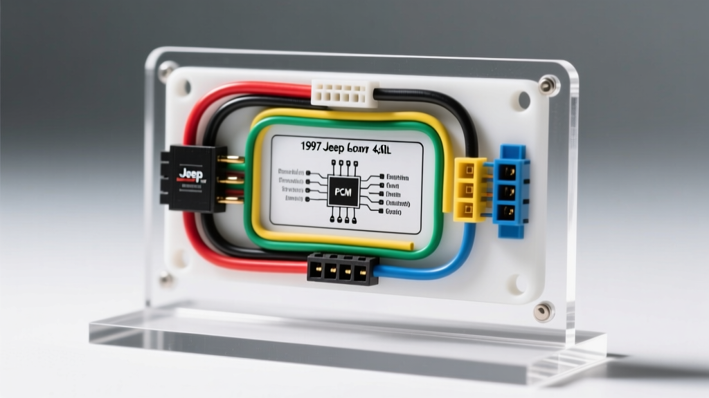
Preparation and Safety Protocols for the 1997 XJ 4.0L
Replacing the main engine wiring harness on a 1997 Jeep Cherokee Sport equipped with the 4.0L AMC inline-6 requires meticulous attention to routing, grounding, and connector integrity. The 1997 model year is a critical transition point for the XJ platform, marking the introduction of the integrated Power Distribution Center (PDC) under the hood and full OBD-II compliance via a revised 32-pin Powertrain Control Module (PCM). Before beginning the harness extraction, you must depressurize the fuel system by removing the fuel pump relay and cranking the engine until it stalls, followed by releasing residual pressure via the Schrader valve on the fuel rail. Disconnect the negative battery terminal at the chassis ground to prevent shorting the 14 AWG Automated Shutdown (ASD) relay feeds during PDC manipulation.
Understanding the 1997 XJ 4.0L Harness Architecture
Unlike pre-1997 models that utilized a 60-pin PCM and a separate fuse block, the 1997 harness integrates directly into the rear of the PDC. The main trunk routes from the PDC, across the firewall, and down to the 32-pin PCM connector located on the passenger side inner fender. From the PCM, the engine branch wraps around the back of the 4.0L cylinder head, feeds the Bosch EV1-style fuel injector connectors, the Camshaft Position Sensor (CMP) in the distributor, and terminates at critical engine block grounds. According to SAE J1128 standards for low-tension primary automotive cable, the 18 AWG sensor and injector control wires used in this harness are rated for continuous operation up to 125°C, but the proximity to the exhaust manifold necessitates high-temperature loom wrapping.
PCM 32-Pin Connector Reference Chart
When diagnosing or splicing a replacement harness, verifying the pinout at the PCM is critical. The 1997 4.0L uses a single 32-pin cavity. Below are the primary circuits you must verify for continuity post-installation:
| Pin Cavity | Circuit Function | Wire Color | AWG Size |
|---|---|---|---|
| Pin 1 | ASD Relay Output (Feed to Injectors/Coil) | Dark Green / Orange | 14 AWG |
| Pin 2 | Injector 1 Control | Dark Blue / Light Green | 18 AWG |
| Pin 3 | Injector 2 Control | Dark Blue / Yellow | 18 AWG |
| Pin 22 | Sensor Ground (CMP, MAP, TPS) | Black / Light Blue | 16 AWG |
| Pin 30 | Camshaft Position Signal | Violet / White | 18 AWG |
| Pin 31 | Ignition Coil Driver | Dark Grey / Black | 16 AWG |
Step-by-Step Harness Removal
- PDC Disconnect: Unlatch the rear retaining tabs on the under-hood PDC. Carefully unplug the three main harness connectors feeding the firewall and engine bay. Do not pull by the wires; use a small pick to release the secondary locking wedges inside the cavities.
- PCM Extraction: Locate the passenger-side PCM. Unbolt the 8mm retaining nuts on the 32-pin connector. Gently wiggle the plug straight out to avoid bending the male terminal pins, which are notoriously fragile on '97-'00 Chrysler PCMs.
- Ground Point Removal: The 1997 4.0L harness relies heavily on G101 and G102. Remove the 8mm bolt securing the G101 ground ring terminal to the dipstick tube stud. Next, remove the G102 ground located on the oil filter adapter housing. Failure to clean these mating surfaces later will result in severe sensor voltage drops.
- Injector and Sensor Unplugging: Depress the wire bail clips on the EV1 injector connectors. Use a specialized EV1 release tool if the plastic housings are brittle from heat cycling. Unplug the alternator field connector, oil pressure sender (1-wire), and coolant temperature sensor (2-wire).
- Valve Cover Loom Removal: Unclip the harness retaining brackets from the valve cover studs. Carefully lift the harness away from the fuel rail, noting the exact routing path behind the engine lifting bracket.
Routing and Installing the Replacement Harness
Installation of the new harness requires replicating factory routing to prevent chafing against the aluminum cylinder head or melting on the exhaust manifold. Begin by feeding the main trunk through the firewall grommet. Apply a dielectric silicone grease to the grommet to prevent tearing the rubber seal, which would allow water ingress into the cabin footwell.
High-Temperature Loom Wrapping
Where the harness crosses the rear of the engine block and drops toward the oxygen sensors, wrap the split-loom tubing in high-heat Tesa cloth tape or fiberglass sleeving. Standard corrugated plastic loom will melt and expose the 18 AWG O2 sensor heater circuits (Brown/White and Brown/Light Green) to the exhaust manifold, causing a dead short and blowing the 15A O2 heater fuse in the PDC.
- Secure the PCM Connection: Inspect the 32-pin PCM plug for pushed-back terminals. Seat the connector fully onto the PCM and torque the 8mm retaining nuts to 25 in-lbs. Over-tightening will crack the PCM solder joints.
- Route Behind the Lifting Bracket: The harness must pass behind the rear engine lifting bracket and under the fuel rail. Use the factory molded loom clips to snap the harness into the valve cover studs.
- Reconnect EV1 Injectors: Push the injector connectors on until you hear a definitive click. Tug gently on the wire pigtail (not the connector body) to verify the internal locking tab has engaged.
- Re-establish Grounds: Wire-brush the G101 dipstick stud and G102 oil filter adapter block surface to bare metal. Apply a thin layer of conductive anti-seize or dielectric grease over the ring terminal after torquing the 8mm bolts to 10 ft-lbs to prevent galvanic corrosion between the copper ring and cast iron block.
Post-Installation Diagnostics and Troubleshooting
Before reconnecting the battery, perform a continuity check on the ASD relay feed (Dark Green/Orange) to ensure no pinched wires exist between the PDC and the injector rail. Reconnect the battery and turn the ignition to the 'ON' position without cranking.
Symptom-Cause-Fix Decision Tree
- Symptom: Engine cranks but no spark, and fuel pump primes for only 2 seconds.
Cause: Loss of Camshaft Position Sensor (CMP) signal or ASD relay failure.
Fix: Backprobe Pin 30 (Violet/White) at the PCM while cranking. If no 5V square wave is present, check the CMP connector inside the distributor for oil contamination or a pushed-back terminal. - Symptom: Engine idles roughly and throws P0201-P0206 (Injector Circuit) codes.
Cause: Poor ground at G101 or bent pins at the PCM.
Fix: Measure voltage drop between the battery negative post and the injector ground circuit with the engine running. A drop greater than 0.1V indicates a corroded G101/G102 ground point. Clean and retorque. - Symptom: Intermittent stalling when hot.
Cause: Crankshaft Position Sensor (CKP) wiring harness chafing.
Fix: Inspect the CKP pigtail routing near the bellhousing. Ensure the harness is secured away from the exhaust downpipe and the flexplate inspection cover.
For comprehensive torque specifications and factory wiring schematics, always cross-reference your work with the Haynes Jeep Cherokee Repair Manual specific to the 1997-2001 XJ generation. Proper harness installation on the 4.0L inline-6 ensures reliable voltage delivery to the high-impedance injectors and prevents the parasitic draws commonly associated with poorly routed aftermarket replacement harnesses.