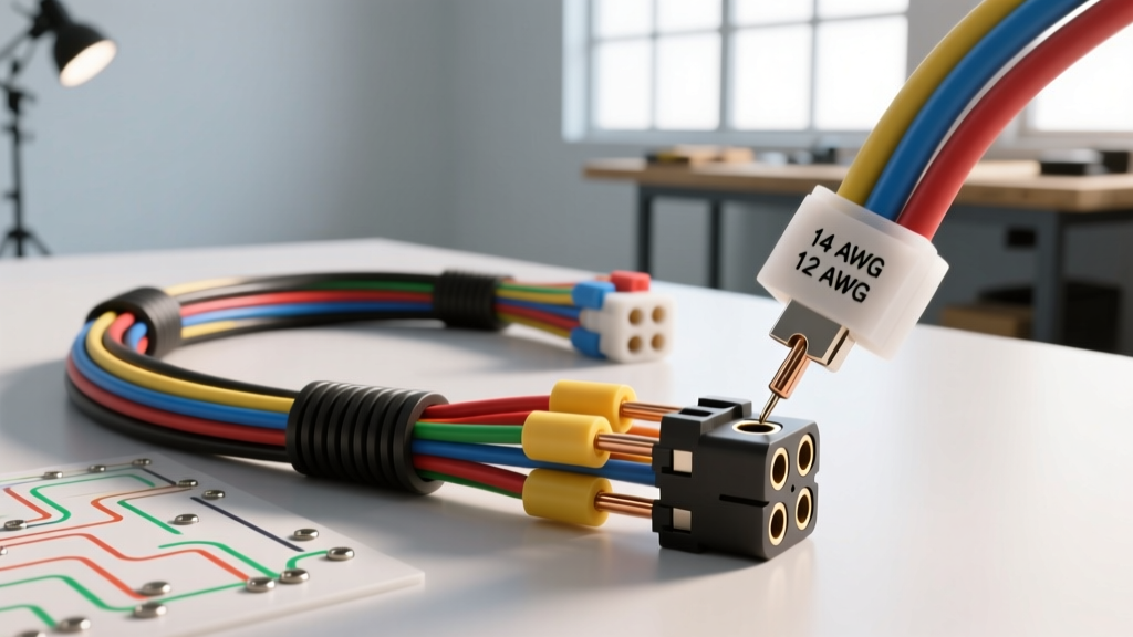
Demystifying the Painless Wiring Harness Universal Kit
When tackling a street rod, restomod, or custom buggy build, the electrical system is often the most intimidating hurdle for beginners. Unlike factory replacement harnesses that plug directly into OEM connectors, a Painless wiring harness universal kit requires the builder to map, route, and terminate circuits manually. Painless Performance Products revolutionized the aftermarket electrical space by providing color-coded, printed, and fused universal harnesses that eliminate the guesswork of raw bulk wire.
However, 'universal' does not mean 'plug-and-play.' A universal harness provides the raw circuits, but the success of your build depends entirely on your understanding of wire gauge, grounding topology, and connector selection. This beginner-friendly guide breaks down the fundamentals of deploying a universal 18-circuit or 21-circuit harness, ensuring your custom vehicle starts, runs, and lights up reliably without melting wires or suffering from voltage drop.
Anatomy of an 18-Circuit Universal Fuse Block
The heart of any Painless universal kit is the fuse block. Most standard street rod builds utilize an 18-circuit kit, which provides dedicated, fused pathways for every major electrical component. Understanding how these circuits are allocated is critical for balancing the electrical load and preventing blown fuses.
| Circuit # | Function | Wire Color | AWG Size | Fuse Rating |
|---|---|---|---|---|
| 1 | Headlights (High/Low) | Blue | 10 AWG | 20A |
| 2 | Taillights & License Plate | Brown | 14 AWG | 15A |
| 3 | Dash & Instrument Lights | Gray | 18 AWG | 5A |
| 4 | Ignition Switch (Run/Start) | Purple | 12 AWG | 20A |
| 5 | Horn & Relay Trigger | Dark Green | 14 AWG | 15A |
| 6 | Wipers & Washer Motor | Light Blue | 14 AWG | 15A |
| 7 | Radio & Accessories (Switched) | Yellow | 14 AWG | 10A |
| 8 | Power Windows / Seats | Red | 10 AWG | 30A |
Notice the correlation between the amperage draw of the component and the American Wire Gauge (AWG) size. High-draw circuits like headlights and power windows utilize 10 AWG wire to minimize resistance and heat generation, while low-draw indicator circuits like dash lights use 18 AWG. Never swap a factory 10 AWG headlight wire for a thinner 14 AWG wire, as the resistance will cause severe voltage drop at the headlight bulb, resulting in dim output and potentially melted insulation.
Wire Gauge (AWG) and Insulation Standards
One of the most common beginner mistakes is using cheap, PVC-insulated bulk wire from a hardware store for automotive applications. Painless universal harnesses utilize GXL (General Cross-Linked) or TXL (Thin-Wall Cross-Linked) wire. According to the SAE J1128 standard for Low Tension Primary Cable, cross-linked polyethylene (XLPE) insulation can withstand continuous operating temperatures up to 125°C (257°F), whereas standard PVC melts and shorts out around 105°C (221°F).
In a custom engine bay where headers and exhaust components are routed tightly, GXL wire is mandatory. Furthermore, TXL wire features a thinner insulation wall than GXL, allowing for smaller overall wire diameters. This makes routing multiple circuits through tight firewall grommets significantly easier without sacrificing amperage capacity. Always verify that any extension wire you splice into your universal harness matches the GXL/TXL specification.
The Grounding Strategy: Avoiding the Floating Ground
If there is one concept that separates professional auto electricians from frustrated beginners, it is grounding topology. Factory vehicles from the 1970s and 1980s often relied on 'daisy-chain' grounding, where one component grounds to the body, and the next component grounds to the first component. In custom builds with painted chassis, powder-coated brackets, and fiberglass bodies, daisy-chaining guarantees a 'floating ground'—a high-resistance path that causes flickering lights and erratic ECU behavior.
As detailed in MAD Electrical's definitive grounding theory, custom builds should utilize a 'Star Ground' or 'Single-Point Ground' system. This involves welding a heavy copper buss bar to the bare metal chassis and running individual, dedicated ground wires from every major component back to that single point.
- Main Battery Ground: Must be 4 AWG or 2 AWG stranded copper, bolted directly to the engine block and the chassis.
- Engine to Chassis Strap: A braided 10 AWG or 8 AWG ground strap is required to ensure the starter motor has a return path, as rubber engine mounts isolate the block from the frame.
- Body Grounds: Run a dedicated 10 AWG ground wire from the firewall to the chassis, and another from the rear taillight housing to the chassis. Do not rely on sheet metal screws through painted steel.
Connector Selection: Weather-Pack vs. Metri-Pack
A universal harness arrives with blunt-cut wires. It is your responsibility to terminate them properly. Never use twist-on wire nuts or electrical tape for automotive connections; vibration and moisture will destroy them. You must use crimped terminals housed in environmentally sealed connectors.
Delphi Weather-Pack Connectors
Weather-Pack connectors are the gold standard for under-hood and exterior connections. They feature a robust silicone rubber seal that protects the brass terminals from moisture and road salt. They are available in 1-way through 6-way configurations. The terminals require a specific ratcheting crimp tool that crimps the wire barrel and the insulation barrel simultaneously. When crimping 14 AWG wire into a Weather-Pack terminal, ensure the wire strands do not splay past the insulation crimp, or the silicone seal will fail to mate.
Metri-Pack 280 Series
For tighter spaces, such as behind the dashboard or connecting to modern EFI sensors, the Metri-Pack 280 series is preferred. These are much smaller, feature a 'pull-to-seat' or 'push-to-seat' locking mechanism, and offer both sealed and unsealed variants. Unsealed Metri-Packs are perfect for interior cabin wiring where moisture is not a concern, keeping the harness bulk to an absolute minimum.
Routing, Looming, and Firewall Penetration
Routing a universal harness requires foresight. Before making a single crimp, lay the entire harness out on the floorboards and mock up the routing paths. The main battery feed (typically a heavy 4 AWG or 6 AWG red wire with a mega-fuse) should be routed separately from the low-voltage sensor wires to prevent electromagnetic interference (EMI), which can confuse modern EFI ECUs.
When passing the harness through the firewall, always use a reinforced rubber firewall grommet. The sharp edges of stamped steel will slice through GXL insulation over time due to engine vibration, causing a direct short to ground and a potential electrical fire. Secure the harness with adhesive-backed wiring clips and nylon zip-ties every 12 to 18 inches.
For under-hood looming, avoid cheap corrugated plastic split-loom in high-heat areas; it becomes brittle and melts. Instead, use expandable braided PET sleeving for a clean, OEM-style look, or high-temp fiberglass/silicone sleeving within 12 inches of exhaust manifolds.
Pre-Flight Voltage Drop Testing
Before connecting the battery and turning the key, you must verify your connections. According to the Painless Performance Wiring Tech Center, the most reliable way to test a newly installed universal harness is via a voltage drop test, not just a simple continuity check.
Set your digital multimeter to DC Volts. Connect the red probe to the battery positive terminal and the black probe to the load side of the component (e.g., the positive terminal of the headlight bulb) with the circuit powered ON. A healthy circuit should show a voltage drop of less than 0.2 volts across the entire length of the wire and connectors. If your multimeter reads a 1.5-volt drop, you have high resistance—likely caused by a poorly crimped terminal, a corroded ground, or a wire gauge that is too thin for the amperage draw.
Mastering a Painless wiring harness universal kit is a rite of passage for custom car builders. By respecting AWG sizing, implementing a dedicated star-ground system, utilizing sealed crimp connectors, and validating your work with voltage drop testing, you will build an electrical system that is not only safe but entirely reliable for years of driving.