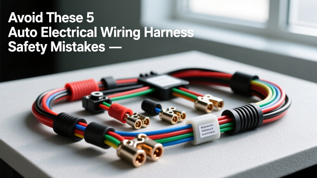
The Hidden Dangers of Harness Routing and Fabrication
When installing a custom or OEM replacement auto electrical wiring harness, the margin for error is effectively zero. Whether you are dropping a GM LS V8 into a classic chassis or upgrading a modern EFI system, the electrical system is the central nervous system of the vehicle. A single frayed wire, an undersized ground, or a poorly placed fuse can lead to catastrophic ECU failure, erratic sensor readings, or a devastating underhood fire.
Many builders approach automotive wiring with a residential or household electrical mindset, which is a recipe for disaster in a high-vibration, high-heat, 12V DC environment. Below, we break down the five most critical safety mistakes made during auto electrical wiring harness installation and how to engineer them out of your build.
Mistake 1: Undersizing Power Wires and Ignoring Voltage Drop
One of the most pervasive errors in harness fabrication is using wire that is too thin for the amperage draw, particularly on long runs from the front-mounted battery to the rear fuel cell. In a 12V DC system, voltage drop is the enemy. If a fuel pump requires 12.5V to maintain 58 PSI of rail pressure, but undersized wiring causes a 2V drop under load, the pump will only see 10.5V. This leads to fuel starvation, lean conditions, and potentially catastrophic engine detonation.
Wire sizing must be calculated based on the SAE International J1128 Standard for high-temperature automotive primary wire, which accounts for the heat under the hood. Household copper wire ratings do not apply here.
SAE J1128 Wire Sizing Reference Chart
| AWG Size | Max Continuous Amps (125°C) | Common LS Swap Application | Max Recommended Length (10ft limit) |
|---|---|---|---|
| 18 AWG | 6A | MAP Sensor, TPS 5V Signal | 10 ft |
| 14 AWG | 15A | Injector Pigtails, Coil Packs | 12 ft |
| 10 AWG | 30A | Fuel Pump Relay Feed | 15 ft |
| 8 AWG | 40A | EFI Main Power Relay Feed | 15 ft |
| 4 AWG | 70A+ | Alternator Main Charge Wire | 20 ft |
For a comprehensive breakdown of voltage drop calculations over distance, consult the Mad Electrical Wire Gauge Guide, which remains an industry-standard reference for motorsport wiring.
Mistake 2: Daisy-Chaining ECU and Sensor Grounds
Daisy-chaining grounds—where multiple components share a single ground wire that passes from one sensor to the next—is a guaranteed way to introduce electrical noise and skewed data into your engine management system. The ECU measures sensor voltage relative to its own internal ground. If the ECU ground and the Throttle Position Sensor (TPS) ground share a wire that carries current from another component, the resistance in that shared wire will create a voltage offset. The ECU will read a false 5.2V reference instead of 5.0V, throwing off your entire fuel map.
Proper Grounding Protocol
- Star Grounding: Run individual ground wires from every major component (ECU, transmission controller, fuel pump) back to a centralized, heavy-duty ground bus bar or directly to the engine block.
- Surface Prep: Never ground to painted metal or powder-coated chassis components. Use a wire wheel or sanding disc to expose bare, shiny metal.
- Hardware: Use M8 or M10 stainless steel ring terminals with internal star washers (DIN 6797) to bite into the bare metal. Torque M8 ground studs to 15-20 Nm to prevent vibration loosening.
- Corrosion Prevention: After torquing, coat the entire ground terminal and exposed metal in dielectric grease or a dedicated battery terminal protector spray to prevent galvanic corrosion.
Mistake 3: Violating the "18-Inch" Fusing Rule
The primary power cable running from the battery positive terminal to the main harness distribution block is the most dangerous wire in the vehicle. It is "hot" at all times, bypassing the ignition switch. If this wire chafes against the chassis or firewall before it reaches the main fuse, it will cause an un-fused dead short, instantly melting the wire insulation and starting an electrical fire.
The Safety Standard: The main Mega Fuse or ANL fuse must be located within 18 inches of the battery positive terminal. For a standard LS swap harness pulling 80 amps at idle and up to 120 amps under heavy electrical load (cooling fans, fuel pump, ECU), a 150A Mega Fuse installed in a sealed, marine-grade fuse holder within 6 inches of the battery is the safest configuration. Never rely on the alternator output stud for main harness power distribution without a dedicated, properly sized fuse.
Mistake 4: Routing Harnesses Near Exhaust and Moving Components
Underhood temperatures can easily exceed 250°F (121°C) near the firewall and 800°F+ near exhaust headers. Standard PVC-jacketed automotive wire (rated to 105°C) will melt, short out, and ignite if routed too close to exhaust manifolds. Furthermore, routing a harness near the steering shaft, suspension components, or throttle linkages without adequate clearance invites physical chafing and wire severing.
Thermal and Physical Protection Specs
- Heat Protection: Any harness branch routed within 12 inches of exhaust headers must be sleeved in silicone fiberglass sleeving (such as Hitfab Tite-Heat), which is rated for continuous 500°F and intermittent 1000°F exposure. Standard plastic split-loom will melt and fuse to the wire in these zones.
- Chafing Protection: Whenever the auto electrical wiring harness passes through a firewall or sheet metal bulkhead, a rubber firewall grommet is mandatory. Use a step-drill bit to create a clean hole, and secure the grommet with RTV silicone to prevent it from vibrating out.
- Clearance: Maintain a minimum 3-inch clearance from all moving suspension and steering components. Use adhesive-backed P-clips (cushioned) on flat, painted surfaces to secure the harness, spacing them no more than 18 inches apart to prevent harness sag.
Mistake 5: Using Solder-Only Joints and Incorrect Crimp Terminals
A common myth in amateur automotive wiring is that soldering wires together is superior to crimping. In a static, household environment, this is true. In a high-vibration automotive environment, solder is a liability. Solder wicks into the stranded copper wire via capillary action, creating a rigid, brittle section of wire. Over time, engine harmonic vibration causes the wire to fatigue and snap exactly at the edge of the solder joint, leading to intermittent misfires or complete electrical failure.
Instead, professional harness builders use open-barrel crimp terminals (such as Delphi Weather-Pack or Metri-Pack 280 series). Proper crimping creates a cold-weld, gas-tight connection that maintains the flexibility of the stranded wire. According to the Mad Electrical Terminal Crimping Guide, a proper open-barrel crimp must exhibit a visible "bellmouth"—a tiny flare of wire strands just past the conductor crimp—ensuring the wire is fully seated without being sheared off by the terminal edges. Always use a dedicated ratcheting crimp tool calibrated for the specific AWG and terminal series to ensure the connection survives the lifespan of the vehicle.
Final Safety Verification Checklist
Before applying battery power to a newly installed auto electrical wiring harness, perform a rigorous multimeter continuity and short-circuit check. Disconnect the ECU and all sensitive solid-state modules. Verify that the main positive feed shows infinite resistance to the chassis ground. Double-check that all high-amperage relays are triggered by low-amperage ECU ground signals, keeping heavy current out of the ECU's internal drivers. By respecting AWG ratings, prioritizing dedicated ground paths, and utilizing motorsport-grade crimping techniques, you ensure your harness is not just functional, but inherently safe.