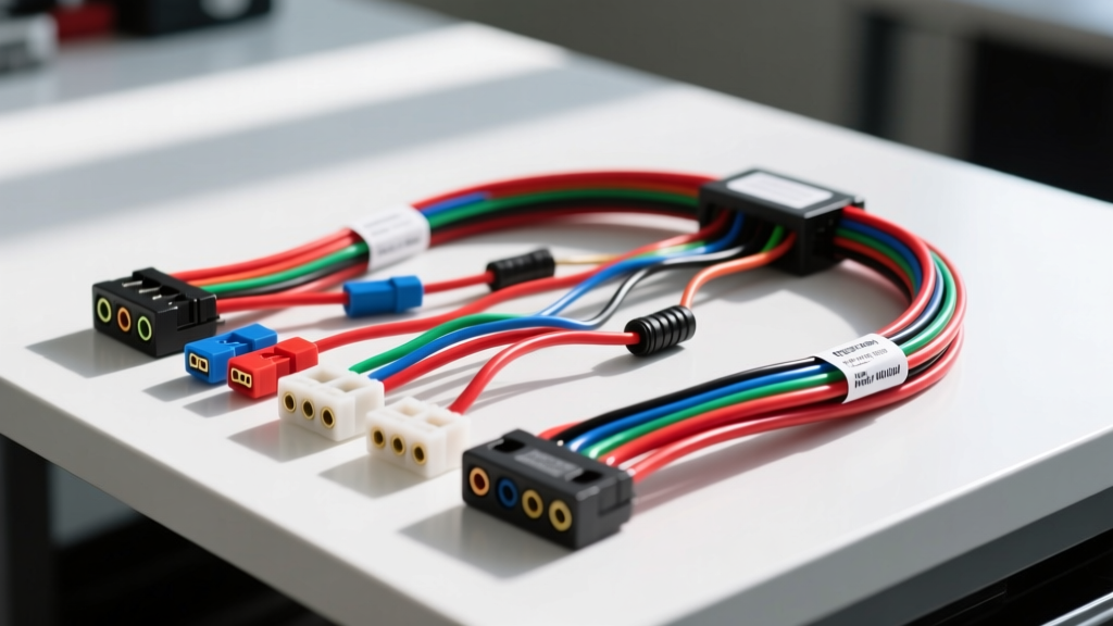
Understanding the Red Wolf Adapter Architecture
When integrating an aftermarket head unit into a factory amplified system—particularly in Nissan, Infiniti, and Toyota platforms—the Red Wolf wiring harness diagram is your primary roadmap. These adapter kits bridge the gap between standard 16-pin ISO/DIN aftermarket radios and proprietary 40-pin or 20-pin OEM connectors. However, misinterpreting the diagram or skipping bench-testing often leads to blown fuses, silent amplifiers, or unresponsive Steering Wheel Controls (SWC). This guide provides a systematic, step-by-step troubleshooting flow to diagnose and resolve the most common installation failures.
Phase 1: Pre-Installation Bench Verification
Before routing the harness behind the dash, you must validate the integrity of the Red Wolf adapter on your workbench. According to standard automotive electrical diagnostics outlined in the AutoShop 101 Electrical Testing Guide, verifying continuity and voltage drops before final assembly saves hours of teardown time.
- Step 1: Connect the 12V Constant (Yellow) and 12V Accessory (Red) wires to a bench power supply set to 13.8V.
- Step 2: Ground the Black wire to the negative terminal.
- Step 3: Using a digital multimeter (DMM), probe the Blue/White amplifier turn-on wire. It should output 12V DC only when the Accessory wire receives power.
- Step 4: Check the CAN-bus lines (if equipped). Measure resistance between CAN-High and CAN-Low. You should read approximately 60 ohms if the harness includes internal termination resistors, or 120 ohms if it relies on the vehicle's OEM termination.
Phase 2: Step-by-Step Symptom Troubleshooting Flow
Symptom A: Factory Amplifier Fails to Turn On (No Audio)
The most frequent issue when consulting a Red Wolf wiring harness diagram for Bose or premium audio retention is a silent factory amplifier. The OEM amp requires a specific wake-up signal, which varies by protocol.
- Verify Remote Turn-On Voltage: Probe the Blue/White wire at the Red Wolf harness connector while the radio is on. If you read 0V, the aftermarket radio's internal amplifier turn-on circuit is disabled in the settings, or the wire is severed.
- Check Data-Bus Wake-Up (CAN-Bus): Many modern Nissan/Infiniti models do not use a 12V analog turn-on wire. Instead, the amplifier wakes up via a CAN-bus message. If your Red Wolf harness features a small black interface module, ensure the Pink (CAN-H) and Purple (CAN-L) wires are not swapped. Swapped CAN lines will result in a U1000 CAN communication DTC and a completely silent audio system.
- Inspect Ground Integrity: The factory amplifier ground is often tied to the harness. Use a DMM to measure voltage drop between the Red Wolf Black ground wire and the vehicle's bare chassis. A reading above 0.1V indicates a high-resistance ground. Scrape the paint and use an 18 AWG ring terminal to secure a dedicated chassis ground.
Symptom B: Steering Wheel Controls (SWC) Unresponsive
Red Wolf harnesses often integrate a resistive ladder network for SWC retention. The Crutchfield Steering Wheel Control Guide notes that these systems rely on precise voltage drops to signal commands.
- Identify the SWC Wires: Locate the Key 1 (or SW1) and Key 2 (or SW2) wires on the Red Wolf diagram. These are typically 20 AWG wires, often colored Purple or Light Green.
- Measure Resistive Ladder Voltage: Back-probe the SWC wire at the head unit harness. With no buttons pressed, you should read 3.3V or 5.0V (depending on the head unit). Pressing 'Volume Up' should drop the voltage to roughly 0.5V, while 'Volume Down' drops it to 1.2V.
- Fixing Voltage Bleed: If the voltages are erratic or hovering near 0V without pressing buttons, you likely have a short to ground in the clock spring, or the Red Wolf interface module is failing to isolate the OEM CAN-bus SWC signals from the analog aftermarket head unit inputs. Ensure you have not accidentally connected both the analog SWC wires AND the CAN-bus SWC wires simultaneously; use only the protocol specified by your head unit manufacturer.
Symptom C: Backup Camera Trigger Failure
- Locate the Reverse Trigger Wire: On the Red Wolf diagram, this is typically an Orange/White or Brown wire.
- Verify 12V Reverse Signal: Shift the vehicle into reverse. Probe the trigger wire. If you read 12V, the harness is functioning, and the fault lies in the aftermarket radio's reverse-camera setting.
- Address PWM Reverse Signals: Late-model vehicles use a Pulse Width Modulated (PWM) signal for the reverse lamp to save power and monitor bulb health. A standard Red Wolf adapter cannot read PWM. You must install a 12V DC relay or a dedicated PWM-to-DC filter module, tapping the 12V Constant wire to provide a clean 12V trigger to the harness.
Reference Table: Standard Red Wolf Nissan/Infiniti Adapter Pinout
Below is a reference chart for a typical Red Wolf 20-pin to 16-pin adapter used in Nissan/Infiniti Bose retention systems. Always cross-reference this with the specific diagram included in your kit, as revisions occur annually.
| Pin | Wire Color | Function | AWG | Diagnostic Note |
|---|---|---|---|---|
| 1 | Yellow | 12V Constant (BATT) | 16 | Fused at 15A. Do not share with high-draw accessories. |
| 2 | Red | 12V Accessory (ACC) | 16 | Controls main head unit wake-up. |
| 3 | Black | Chassis Ground | 16 | Must have < 0.1V drop to chassis. |
| 4 | Blue/White | Amp Turn-On (Remote) | 18 | Max 300mA output. Use a relay for multiple amps. |
| 5 | Orange/White | Illumination / Dimmer | 20 | Provides 12V when parking lights are on. |
| 6 | Pink | CAN-High | 20 | Idle voltage ~2.5V. Do not ground. |
| 7 | Purple | CAN-Low | 20 | Idle voltage ~2.5V. Swapping causes U1000 DTC. |
| 8 | Light Green | SWC 1 (Key 1) | 22 | Analog resistive ladder input. |
| 9 | Brown | Reverse Trigger | 18 | Requires clean 12V DC, not PWM. |
Advanced Diagnostics: Managing Electromagnetic Interference (EMI)
When routing the Red Wolf harness through the dashboard, improper wire management can lead to alternator whine or CAN-bus corruption. According to SAE J1113 standards for Electromagnetic Compatibility, low-voltage data lines must be segregated from high-current power lines.
- Separation Rule: Keep the 16 AWG power and ground wires on the opposite side of the steering column from the 20 AWG CAN-bus and SWC wires.
- Shielding: If your Red Wolf kit includes a foil-wrapped shield wire for the CAN-bus lines, ensure it is grounded at ONE end only (preferably the interface module side) to prevent ground loops.
- Crimping Standards: Avoid twisting and taping wires. Use insulated butt connectors with heat-shrink adhesive lining, or use a ratcheting crimper for closed-end barrel connectors. A poor crimp on a 22 AWG SWC wire will introduce resistance, altering the voltage ladder and causing the head unit to misinterpret button presses.
Final Validation Protocol
Once all connections are verified against the Red Wolf wiring harness diagram, perform a full system reboot. Disconnect the vehicle's negative battery terminal for 10 minutes to clear any lingering CAN-bus DTCs and reset the OEM Body Control Module (BCM). Reconnect the battery, turn the ignition to the ON position, and verify that the head unit boots, the factory amplifier engages without a popping sound, and all SWC functions map correctly. By adhering to this structured troubleshooting flow, you eliminate guesswork and ensure a reliable, factory-grade integration.