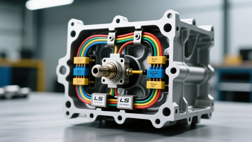
Knock Sensor Wiring Harness Troubleshooting Flow
The knock sensor is the engine management system's primary defense against catastrophic detonation. Operating on a piezoelectric principle, the sensor acts as a calibrated microphone, generating a high-impedance AC millivolt signal proportional to engine block vibration. Because this signal is exceptionally sensitive, the knock sensor wiring harness is just as critical as the sensor itself. If the harness shielding is compromised, electromagnetic interference (EMI) from the alternator, ignition coils, or fuel injectors will mimic the frequency of engine knock, forcing the Powertrain Control Module (PCM) to aggressively pull ignition timing.
This guide provides a definitive, step-by-step diagnostic flow for troubleshooting knock sensor wiring harness faults, with a specific focus on the notoriously problematic GM LS V8 (Gen III/IV) valley cover harness architecture. According to SAE J1113 Electromagnetic Compatibility standards, high-impedance sensor circuits require meticulous shielding and routing to prevent signal degradation.
Diagnostic Decision Tree: Symptom to Root Cause
Before unbolting components, use this decision tree to isolate the fault domain based on your OBD-II data and scan tool live streams.
- Symptom: DTC P0327 (Knock Sensor 1 Low Voltage) or P0332 (Knock Sensor 2 Low Voltage) sets immediately at key-on-engine-off (KOEO).
- Probable Cause: Hard short to ground in the harness, or severe connector fretting corrosion at the PCM.
- Action: Proceed to Step 2 (Multimeter Continuity Test).
- Symptom: Codes set only under heavy load or high RPM; noticeable power loss.
- Probable Cause: Harness shield degradation allowing EMI intrusion, or internal wire chafing that only shorts when the engine torques over under load.
- Action: Proceed to Step 3 (Shield Integrity) and Step 4 (Oscilloscope Verification).
- Symptom: Random misfires, erratic timing retard at idle, no hard DTCs.
- Probable Cause: Oil ingress into the valley cover connector causing cross-talk between Sensor 1 and Sensor 2 signal wires.
- Action: Proceed to Step 1 (Visual & Physical Inspection).
Step 1: Visual and Physical Inspection
On GM LS V8 platforms, the knock sensors are mounted beneath the intake manifold in the lifter valley. The factory harness is subjected to extreme thermal cycling and oil vapor. Begin your inspection by removing the intake manifold to access the valley cover.
- Inspect the Teflon/Nylon Sheathing: Look for micro-cracking or brittleness. Heat from the block degrades standard PVC wire insulation; if the harness sheathing flakes off when bent, the internal 20 AWG conductors are likely compromised.
- Check for Oil Ingress: The valley cover gasket often weeps. If engine oil has pooled in the sensor cavity, it can wick up into the harness connector via capillary action, altering the dielectric constant of the connector and causing signal cross-talk.
- Examine the Shield Drain Wire: Trace the bare copper braided shield from the sensor pigtail to the main harness loom. Ensure the shield has not been pinched between the intake manifold and the cylinder head, which would create an unintended ground loop.
Step 2: Multimeter Continuity and Resistance Testing
Disconnect the battery and unplug the PCM Connector C1 (Blue). Use a high-quality Digital Multimeter (DMM) with a resolution of at least 0.01 ohms to test the harness.
| Test Point | Specification | Failure Mode Indicator |
|---|---|---|
| PCM Pin 11 (Dark Blue) to Sensor Pin A | < 0.5 Ohms | > 1.0 Ohms indicates internal wire corrosion or a failing crimp terminal. |
| PCM Pin 12 (White) to Sensor Pin B | < 0.5 Ohms | > 1.0 Ohms indicates internal wire corrosion or a failing crimp terminal. |
| PCM Pin 11 to Chassis Ground | OL (Open Loop) | Any resistance reading indicates the signal wire is chafing against the block. |
| PCM Pin 12 to Chassis Ground | OL (Open Loop) | Any resistance reading indicates the signal wire is chafing against the block. |
Expert Note: Never use a standard test light or apply 12V power to a knock sensor circuit. The PCM's internal pull-up/pull-down resistors and the piezoelectric element are highly sensitive to overvoltage. As detailed in Helm Incorporated OEM Service Manuals, applying external voltage can permanently fry the PCM's analog-to-digital knock processing channel.
Step 3: Shield Integrity and Ground Loop Verification
The most common cause of phantom knock (timing pull without actual detonation) is a broken shield. The shield must act as a Faraday cage, absorbing EMI and routing it to ground. Crucially, the shield must only be grounded at the PCM end, not at the sensor end. Grounding both ends creates a loop antenna that will amplify alternator whine directly into the PCM.
- Set your DMM to the continuity/beep setting.
- Probe the bare copper drain wire at the sensor connector and the designated shield ground pin at the PCM harness.
- You should read < 1.0 Ohm. If the circuit is open, the braided shield has snapped under the harness loom, rendering the harness useless in high-EMI environments.
- Check for shield-to-signal shorts: Probe the shield drain wire and Pin 11/Pin 12. The reading must be OL (Open Loop). If there is continuity, the shield has pierced the 20 AWG wire insulation inside the loom.
Step 4: Oscilloscope Signal Verification
A multimeter cannot capture the high-frequency AC transients of a knock event. To definitively diagnose a noisy harness versus a failing sensor, you must use an automotive oscilloscope.
- Connect the scope probes to the Dark Blue and White signal wires using back-probes at the PCM connector to maintain circuit integrity.
- Set the scope to AC Coupling, 50mV/div, and a timebase of 10ms/div.
- Start the engine and let it idle. A healthy harness will show a relatively flat baseline with minor, uniform mechanical noise (valvetrain clatter).
- Take a brass hammer (never use steel, as it alters the acoustic frequency and can damage the block) and tap the engine block near the sensor.
- Waveform Analysis: You should see a clean, high-amplitude AC sine wave decay. If the baseline is 'fuzzy' or shows high-frequency spikes that correlate with alternator RPM, the harness shielding has failed, allowing EMI to corrupt the signal. According to Bosch Automotive Electrics, the PCM's digital signal processor relies on a clean frequency window (typically 5kHz to 15kHz for LS V8s); harness EMI outside this window can still trigger false knock retard if the amplitude is high enough.
Repair vs. Replacement: Why Harness Kits are Mandatory
When a knock sensor wiring harness fails, the instinct is to cut out the damaged section and splice in new wire. Do not do this. Standard primary wire (GXL/TXL) lacks the necessary braided shielding. Furthermore, splicing shielded wire requires specialized solder-sleeve shield terminations to maintain the capacitance and continuity of the Faraday cage. A poorly spliced shield creates an impedance mismatch, reflecting high-frequency signals back into the PCM.
The only reliable repair protocol is the installation of a complete, pre-terminated knock sensor wiring harness kit. When installing a replacement harness (such as an aftermarket valley cover relocation harness or an OEM replacement pigtail):
- Wrap the new harness in high-temperature fiberglass or Teflon loom to resist manifold heat.
- Apply a dab of dielectric grease to the 2-way sensor connector to prevent moisture and oil vapor ingress.
- Ensure the harness is routed away from the front of the block where it can be snagged by the accessory drive belt or chafe against the water pump housing.
- Use high-temp RTV silicone to seal the valley cover harness pass-through, preventing oil from migrating into the PCM connector bay.
By following this structured diagnostic flow, you can accurately differentiate between a failed piezoelectric sensor and a compromised wiring harness, saving hours of misdiagnosis and preventing catastrophic engine damage from undetected detonation.