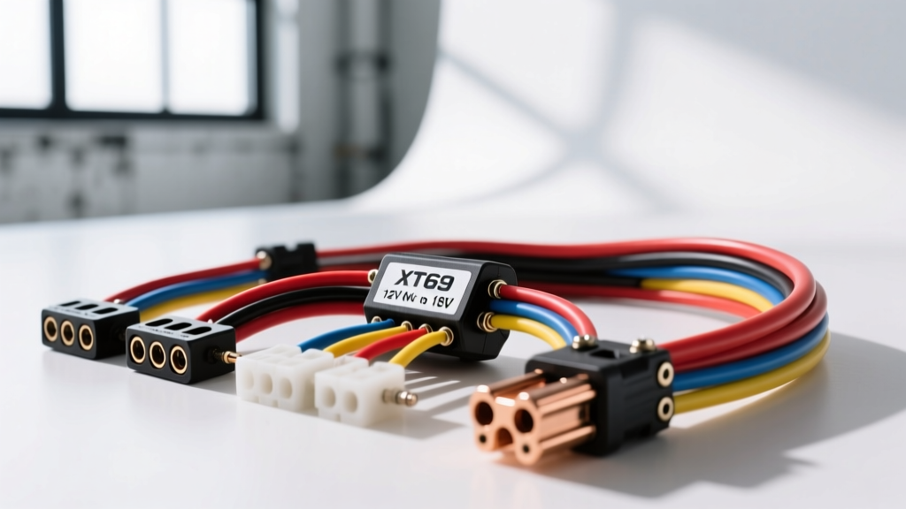
Why the OEM Power Wheels Wiring Harness Fails Under Higher Voltage
The factory wiring harness in most 12V Power Wheels vehicles is engineered for a strict 12V sealed lead-acid (SLA) battery and a maximum continuous draw of 15 to 20 amps. OEM manufacturers typically utilize 16 AWG or 18 AWG copper-clad aluminum (CCA) wire with thin PVC insulation and cheap stamped spade connectors. When enthusiasts upgrade to an 18V lithium-ion tool battery or a 24V SLA configuration, the increased voltage pushes the motors to spin faster, which exponentially increases the amperage draw under load. This causes the OEM harness to act as a resistor, generating severe heat, melting the pedal switch connectors, and creating a significant fire hazard.
Building a custom, high-amperage power wheels wiring harness is the only safe way to run 18V or 24V setups. This guide details the complete fabrication and installation of a heavy-duty harness using 14 AWG silicone wire, XT60 battery connectors, and a 30A automotive relay to bypass the fragile factory pedal switch.
Essential Components and Wire Specifications
Before tearing down the vehicle, gather the correct materials. According to SAE J1128 standards for low-tension primary cable, wire insulation and stranding are critical for DC automotive applications where vibration and tight chassis bends are present. Silicone-insulated wire is mandatory for this application due to its high strand count and heat resistance.
| Component | Specification | Purpose in Harness |
|---|---|---|
| Main Power Wire | 14 AWG Stranded Silicone (Tinned Copper) | Main trunk from battery to relay and motors |
| Signal/Trigger Wire | 18 AWG PVC or Silicone | Pedal switch to relay coil (Pin 86) |
| Battery Connector | XT60 (Male/Female Pair) | High-amperage, spark-resistant battery disconnect |
| Main Relay | 12V/24V 30A Bosch-Style SPDT Relay | Handles motor stall current; saves pedal switch |
| Overcurrent Protection | 40A ANL Fuse with Holder | Replaces factory thermal breaker for fast trip times |
| Connectors | 1/4-inch Fully Insulated Female Spade | Secure connection to gearbox and FWD/REV switches |
Step-by-Step Power Wheels Wiring Harness Installation
Step 1: Removing the Factory Harness and Pedal Switch
Disconnect the 12V battery and remove it from the chassis. Trace the factory wiring harness from the battery to the forward/reverse rocker switch (usually a DPDT switch located on the dashboard or shifter), and down to the foot pedal. Unplug the spade connectors from the pedal switch and the gearbox motors. Note the routing of the wires through the chassis holes. Use a multimeter to verify zero voltage across the main power leads before cutting the factory harness out of the vehicle. Retain the factory DPDT forward/reverse switch if it is in good condition, but discard the factory thermal breaker and pedal switch if the spade terminals show signs of thermal discoloration.
Step 2: Building the Main Power Trunk with XT60 and ANL Fuse
The main power trunk begins at the battery box. Solder a female XT60 connector to two 12-inch lengths of 14 AWG wire (Red for positive, Black for negative). Pro-Tip: To prevent melting the XT60 plastic housing during soldering, use a heat-sink clip or hold the wire with hemostats to absorb excess heat. Always apply rosin-core flux before applying 60/40 leaded solder to the tinned copper strands.
On the positive (Red) wire exiting the XT60, splice in a 40A ANL fuse holder within 6 inches of the battery connection. This ensures that in the event of a dead short against the metal chassis or a seized gearbox, the fuse will blow before the wire insulation catches fire. Route the positive and negative 14 AWG wires through the chassis toward the central dashboard area where the relay will be mounted.
Step 3: Wiring the 30A Relay and High-Amp Pedal Switch Bypass
The most critical upgrade in this power wheels wiring harness is removing the motor load from the foot pedal. The OEM pedal switch is a simple micro-switch rated for roughly 10 amps. Running 18V through it will melt the contacts. Instead, we use the pedal switch merely as a low-amp signal trigger for a heavy-duty relay. Referencing standard automotive relay pinout configurations, wire the 5-pin Bosch-style relay as follows:
- Pin 30 (Common Input): Connect to the positive 14 AWG wire coming from the ANL fuse.
- Pin 87 (Normally Open Output): Connect to a 14 AWG red wire that will feed the center pins of the Forward/Reverse DPDT switch.
- Pin 85 (Coil Ground): Connect to the main 14 AWG black ground wire, or directly to the vehicle chassis if a clean bare-metal grounding point is available.
- Pin 86 (Coil Trigger): Connect to an 18 AWG wire that routes down to the foot pedal switch.
Wire the other side of the foot pedal switch to a positive 12V/18V source. When the child presses the pedal, it sends a low-amp signal to Pin 86, energizing the coil and closing the high-amp circuit between Pin 30 and Pin 87. This completely eliminates heat buildup at the pedal.
Step 4: Wiring the DPDT Forward/Reverse Switch
The factory shifter is typically a 6-pin Double Pole Double Throw (DPDT) switch. To wire this into your new 14 AWG harness, you must create an 'X' crossover pattern on the back of the switch to reverse the polarity sent to the motors.
- Identify the 6 pins (two rows of three).
- Connect the positive 14 AWG wire from Relay Pin 87 to the top-left pin.
- Connect the main 14 AWG ground wire to the top-right pin.
- Use two short jumper wires to cross the middle pins to the opposite outer pins (Middle-Left jumps to Bottom-Right; Middle-Right jumps to Bottom-Left).
- The Bottom-Left and Bottom-Right pins are your motor outputs. Run 14 AWG wires from these pins back to the positive and negative terminals on the gearbox motors.
Step 5: Routing, Looming, and Securing the Harness
DC low-voltage systems are highly susceptible to voltage drop if wires are stretched, pinched, or routed near moving parts. Wrap the entire 14 AWG power trunk in split-loom tubing to protect against abrasion from the plastic chassis mold lines. Use UV-resistant zip ties to secure the harness every 6 to 8 inches. Crucially, ensure the harness is routed entirely clear of the steering column gears, the rear drive axle, and any suspension linkages. Leave enough slack near the gearboxes to accommodate suspension travel without putting tension on the spade connectors.
Troubleshooting Common Voltage Drop and Heat Issues
Even with a custom power wheels wiring harness, improper terminations can cause failures. If the vehicle runs sluggishly on 18V or the gearboxes emit a humming sound without turning, perform the following diagnostics:
- Voltage Drop Test: Set your multimeter to DC Volts. Place one probe on the battery positive terminal and the other on Relay Pin 30 while the pedal is pressed. A reading above 0.2V indicates a poor crimp or solder joint at the XT60 or ANL fuse holder.
- Spade Connector Tension: The most common failure point at the gearbox is loose 1/4-inch spade connectors. Use needle-nose pliers to slightly squeeze the female spade connector before sliding it onto the motor tab. It should require deliberate force to push on and pull off.
- Brake Pedal Interference: If your model features a high/low speed switch or a brake pedal interrupt, ensure these secondary switches are bypassed or upgraded to handle the 18V/24V current, otherwise they will become the new bottleneck and melt.
By upgrading to a 14 AWG silicone-based power wheels wiring harness and isolating the motor load via a 30A relay, you ensure the vehicle can safely handle the immense torque and amperage spikes generated by 18V and 24V lithium or SLA battery conversions.