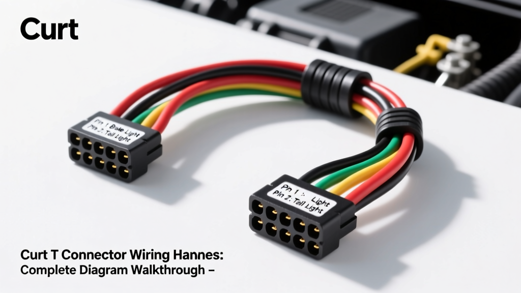
Introduction to Curt T-Connector Wiring Systems
The Curt T connector wiring harness represents the industry standard for integrating trailer lighting into modern vehicle electrical architectures. Unlike older, invasive splice-and-solder kits, a T-connector harness utilizes custom-molded OEM-style plugs (often conforming to USCAR standards) to tee directly into the factory tail light assemblies or rear junction blocks. However, the physical connection is only half the engineering equation. The heart of the Curt T-connector system is the powered converter module, designed to isolate the vehicle’s sensitive Controller Area Network (CAN bus) and Body Control Module (BCM) from the heavy current draw of trailer lighting.
This complete diagram walkthrough will dissect the pinouts, wire color codes, AWG specifications, and multiplex filtering logic required to properly install, diagnose, and optimize a Curt T-connector harness on modern multiplexed vehicles.
The 4-Way Flat Connector: Pinout and Wire Color Walkthrough
The output side of the Curt T-connector system terminates in a standard 4-way flat trailer connector. Adhering to SAE J578 lighting color standards, the trailer-side wiring utilizes a specific color-coded matrix to ensure cross-compatibility between all North American trailers and tow vehicles.
| Pin Position | Function | Wire Color | AWG Rating | Typical Amperage Draw |
|---|---|---|---|---|
| 1 (Exposed/Ground) | Chassis Ground / Return Path | White | 14 - 16 AWG | N/A (Carries total return load) |
| 2 (Inner Left) | Tail / Running / Marker Lights | Brown | 18 AWG | 2.0A - 4.0A |
| 3 (Inner Right) | Left Turn Signal / Stop Lamp | Yellow | 18 AWG | 2.0A - 4.0A |
| 4 (Outer Right) | Right Turn Signal / Stop Lamp | Green | 18 AWG | 2.0A - 4.0A |
Signal Sensing vs. Power Switching
It is critical to understand that the Yellow, Green, and Brown wires on the vehicle side of the Curt converter module are signal sensing wires. They are typically 18 AWG stranded copper and are designed to read voltage states or Pulse Width Modulation (PWM) frequencies from the OEM tail light circuit. They do not supply power to the trailer. The actual current for the trailer is sourced from the dedicated 12V power feed wire and switched through internal MOSFETs inside the converter module.
Converter Module Logic: Protecting Multiplex Networks
Modern vehicles (e.g., 2015+ Ford F-150, 2018+ Jeep Wrangler, and most European imports) utilize multiplexed wiring networks and solid-state BCM relays to monitor exterior lighting. The BCM expects a specific current draw and resistance profile for the tail lights. If you wire a trailer directly to these circuits, the additional 4 to 8 amps of draw will cause the BCM to register a "short to ground" or "bulb out" fault, subsequently cutting power to the circuit entirely.
Opto-Isolation and PWM Filtering
The Curt T-connector module solves this using high-impedance opto-isolators. The module "reads" the OEM voltage signal without drawing meaningful current (typically less than 10 milliamps). Furthermore, many modern vehicles use PWM to dim daytime running lights or regulate taillight brightness. The Curt module features an internal microcontroller that filters out high-frequency PWM noise, ensuring the trailer lights only illuminate when a sustained 12V+ DC threshold is met. This prevents the trailer lights from flickering or staying on when the vehicle is off but the CAN bus is still awake.
Step-by-Step Wiring Diagram Routing Guide
A proper installation requires strict adherence to routing and termination protocols to prevent voltage drop and electromagnetic interference (EMI).
1. USCAR Connector Tee-In Integration
Locate the factory USCAR 6-pin or 8-pin connector behind the rear bumper cover or near the spare tire well. Disconnect the OEM plug and insert the Curt T-connector inline. Ensure the locking tab engages with an audible click. Apply a small amount of Nyogel 760G dielectric grease to the connector weather seals to prevent galvanic corrosion and moisture ingress, which is the leading cause of parasitic battery drain in T-connector systems.
2. The 12V Power Feed Routing
The Black wire on the Curt module is the 12V+ power feed. This wire must be routed from the rear converter module to the vehicle’s positive battery terminal.
- Wire Gauge: Use the provided 12 AWG copper wire. Do not downsize to 14 AWG, as a 20-foot run carrying 10A will experience a voltage drop exceeding 0.5V, potentially causing the module’s low-voltage lockout to trigger.
- Routing Path: Route the wire along the factory frame rail harness. Secure with UV-resistant zip ties every 12 inches. Maintain a minimum 6-inch clearance from exhaust components and moving suspension linkages.
- Fusing: Terminate the wire at the battery using a ring terminal over the positive post, after the inline 20A or 30A ATO/Maxi fuse holder. The fuse must be within 6 inches of the battery terminal to protect the entire length of the 12 AWG wire from a dead short.
3. Grounding Protocols (The White Wire)
The White ground wire must be bonded to a clean, bare metal surface on the vehicle’s unibody or frame rail. Do not rely on factory bolt threads that may be coated with e-coat or rust-preventative compounds. Use a #10 or #12 self-tapping sheet metal screw with a star washer to bite through the top layer of steel. Coat the terminal with dielectric grease after torquing to seal out moisture.
Troubleshooting the T-Connector Circuit
When diagnosing a Curt T connector wiring harness, technicians must isolate whether the fault lies on the vehicle side (input), the module itself, or the trailer side (output). Refer to the following diagnostic decision tree based on common field failures documented in Curt Manufacturing’s technical bulletins.
| Symptom | Probable Cause | Diagnostic / Fix Procedure |
|---|---|---|
| Trailer running lights flash rapidly or strobe. | PWM signal from vehicle BCM misinterpreted by module. | Verify module is a "PWM-compatible" Curt part number. Check for loose ground on White wire causing floating voltage reference. |
| No trailer lights; Vehicle BCM throws "Tail Light Out" dash warning. | Module internal short or moisture ingress drawing current from OEM signal wire. | Disconnect module from OEM USCAR plug. Clear BCM codes via OBDII scanner. Test OEM plug with a high-impedance multimeter. Replace Curt module if internal short is confirmed. |
| Left turn signal activates, but right trailer tail light also dims on. | Bad trailer ground causing "backfeeding" through the dual-filament bulb sockets. | The issue is NOT the Curt harness. Inspect the trailer’s main ground wire and individual lamp housing grounds. Clean bare metal contact points on the trailer frame. |
| Converter module becomes excessively hot to the touch. | Overloaded circuit or undersized 12V power feed wire. | Measure amperage on the Black 12V+ wire with a clamp meter. Ensure total trailer draw does not exceed the module’s rated capacity (typically 7.5A per circuit). Check for corroded inline fuse holder causing resistance heat. |
Advanced Integration: 3-Wire to 2-Wire Signal Combining
Many modern Asian and European vehicles utilize a "3-wire" lighting system: one dedicated wire for the tail light, one for the brake light, and one for the turn signal. North American trailers use a "2-wire" combined system where the brake and turn signals share the same circuit (Yellow and Green). The Curt T-connector module contains internal logic gates that automatically combine the separate brake and turn inputs from the vehicle into the unified output required by the 4-way flat trailer connector. When installing on a 3-wire vehicle, ensure you are tapping the dedicated turn signal wires behind the tail light housing, rather than the high-mount third brake light wire, to prevent hyper-flashing and logic conflicts.
Summary and Best Practices
The Curt T connector wiring harness is a highly engineered bridge between sensitive automotive networks and rugged trailer environments. Success relies on respecting the difference between signal sensing and power delivery, adhering to strict 12 AWG power feed requirements, and executing flawless, bare-metal ground terminations. For further reading on federal lighting mandates that dictate these trailer wiring configurations, consult the NHTSA FMVSS 108 documentation regarding exterior lighting and reflective devices.