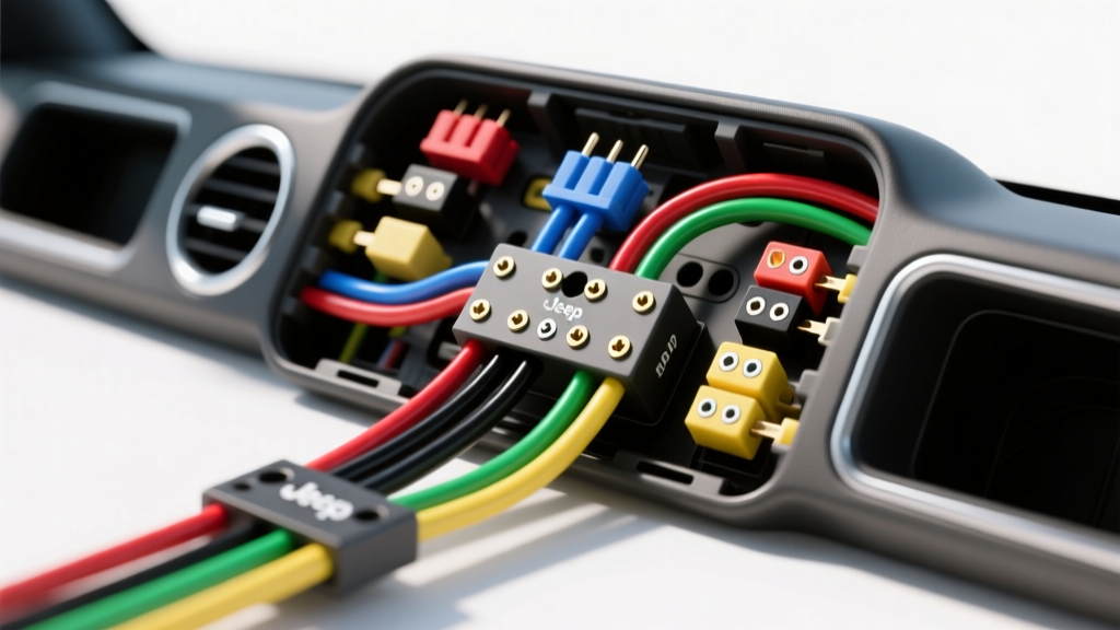
The Hidden Dangers of Guessing Jeep Radio Wiring Harness Color Codes
Upgrading the head unit in a Jeep Wrangler JK (2007-2018) or Grand Cherokee WK is one of the most common modifications in the off-road community. However, the transition from simple analog 12-volt systems to multiplexed data networks has turned the factory radio wiring harness color code matrix into a minefield for the uninitiated. Unlike older vehicles where a red wire was always switched power and black was always ground, modern Jeeps utilize the Controller Area Network (CAN bus) to transmit critical vehicle data through the radio chassis. Misinterpreting these color codes or attempting to splice an aftermarket stereo directly into the factory harness without proper interfaces is a leading cause of catastrophic electrical failures, instrument cluster blackouts, and permanent module lockouts.
As an automotive electrical specialist, I have diagnosed countless Jeep electrical gremlins stemming from a single misunderstood wire. This guide breaks down the exact factory pinouts, highlights the most destructive mistakes DIYers make, and provides actionable safety warnings to protect your Jeep's sensitive Totally Integrated Power Module (TIPM) and Body Control Module (BCM).
Why the CAN Bus System Changes Everything
Before touching a wire stripper, you must understand that the factory radio in a modern Jeep is not just an audio receiver; it is a registered node on the vehicle's high-speed CAN C network. According to the SAE J2284 High-Speed CAN Standard, this network relies on differential signaling between two twisted wires to transmit data at speeds up to 500 kbps. The CAN C (+) and CAN C (-) wires operate at nominal voltages of 2.5V. If you mistakenly connect a 12V accessory lead to either of these data lines based on a misread color code, you will instantly fry the CAN transceiver chips inside the BCM, TIPM, or instrument cluster, resulting in thousands of dollars in replacement and programming costs.
Critical Jeep Wrangler JK & WK Radio Pinout & Color Code Reference
The most common factory connector for Jeep radios of this era is the 22-pin Molex connector. Below is the definitive reference for the critical power, ground, and data circuits. Always verify these with a digital multimeter (DMM) before making any connections, as previous owners or dealerships may have repinned connectors.
| Pin | Wire Color | Function | AWG Size | Safety Warning |
|---|---|---|---|---|
| 1 | White/Green | CAN C (+) Data | 22 AWG | Never probe with a test light; 12V will destroy the network. |
| 2 | White/Orange | CAN C (-) Data | 22 AWG | Must maintain 120-ohm twisted pair impedance. |
| 7 | Red/White | Fused B+ (Battery Constant) | 16 AWG | Memory feed; do not exceed 10A draw without inline fuse. |
| 14 | Black/Light Green | Chassis Ground | 16 AWG | Do not rely on radio chassis mounting bolts for ground. |
| 16 | Pink/Yellow | Fused Ignition (Run/Start) | 18 AWG | TIPM monitored; overcurrent will hard-lock the circuit. |
| 17 | White/Black | Illumination / Dimmer | 20 AWG | PWM signal on some trims; verify with DMM. |
5 Fatal Wiring Mistakes That Destroy Jeep Electrical Systems
Mistake 1: Probing the CAN Bus with a Test Light
The most common and destructive mistake occurs when installers use a standard incandescent test light to verify wire functions. A typical automotive test light draws between 50mA and 100mA at 12 volts. When you pierce the insulation of the White/Green (Pin 1) or White/Orange (Pin 2) CAN bus wires with a test light, the sudden current draw and voltage spike overwhelm the delicate differential transceivers. Safety Fix: Only use a high-impedance Digital Multimeter (DMM) set to DC Volts when verifying data lines. Furthermore, use precision micro-strippers designed for 22-24 AWG wire; using standard 18-22 AWG strippers often nicks the copper strands, altering the impedance of the twisted pair and causing intermittent data dropouts that manifest as random stalling or transmission limp-mode.
Mistake 2: Overloading the TIPM Accessory Feed
The Pink/Yellow wire on Pin 16 provides switched 12V ignition power. In older vehicles, installers would splice into this wire to trigger aftermarket amplifiers or LED light bars. In modern Jeeps, this circuit is routed directly through the Totally Integrated Power Module (TIPM). The TIPM utilizes solid-state smart fuses that monitor current draw in real-time. The factory radio only draws a fraction of an amp on this circuit. If you splice an amp turn-on wire or a relay coil into the Pink/Yellow wire and the draw exceeds the TIPM's programmed threshold (usually around 2A to 5A for this specific circuit), the TIPM will detect an overcurrent fault and permanently shut down the power feed to that pin. You cannot simply replace a physical fuse; the TIPM must be reset using a dealer-level WiTech diagnostic scanner. Safety Fix: Always use the remote turn-on output from your aftermarket head unit or a dedicated data interface to trigger external amplifiers, leaving the factory Pink/Yellow wire completely isolated.
Mistake 3: Confusing Illumination with the Data Bus
Visually, the White/Black illumination wire (Pin 17) looks remarkably similar to the White/Green CAN C (+) wire (Pin 1), especially in dim garage lighting or when the wires are coated in factory dielectric grease. Splicing a 12V accessory into the illumination circuit can backfeed voltage into the BCM's dimmer control module, causing interior lighting to flicker or blowing the BCM driver transistor. Safety Fix: Clean the wire insulation with isopropyl alcohol before identification, and always trace the wire back at least two inches into the loom to verify the secondary tracer color against the Chrysler TechAuthority Service Manuals.
Mistake 4: Poor Grounding Practices and Alternator Whine
Many DIYers assume that because the factory radio is bolted to the metal dashboard, the chassis ground (Pin 14, Black/Light Green) is optional. This is a massive error. The Jeep's dashboard is painted and powder-coated, creating a high-resistance barrier. Relying on the chassis for ground forces the radio to seek a ground path through the CAN bus shield or internal audio RCA grounds, creating a massive ground loop. This results in severe alternator whine that scales with engine RPM and can eventually damage the internal audio output ICs of your new head unit. Safety Fix: Always connect the 16 AWG Black/Light Green ground wire directly to the aftermarket harness ground, and ensure the connection is crimped using a marine-grade heat-shrink butt connector, not a twist-on wire nut which will vibrate loose on off-road trails.
Mistake 5: Cutting the Factory Connector Off Completely
In a rush to finish an install, some technicians simply snip the factory 22-pin Molex connector off the vehicle harness and use butt connectors to mate it to an aftermarket wiring pigtail. This destroys the vehicle's resale value, makes reverting to stock impossible, and exposes the delicate 22 AWG CAN wires to the elements and vibration. Safety Fix: Never cut the factory harness. Always use a vehicle-specific T-harness or data interface.
Safety Warnings: Protecting the TIPM and BCM with Proper Interfaces
To safely bypass the dangers of the Jeep radio wiring harness color code matrix, you must retain the factory data communication while extracting clean, isolated analog power for your aftermarket stereo. This is achieved using a data retention interface such as the PAC RP4-CH11 or the iDatalink Maestro RR. These modules plug inline between the factory Jeep harness and the new radio, reading the CAN bus data digitally and outputting safe, isolated 12V accessory, illumination, and amplifier turn-on signals. For detailed compatibility matrices and installation diagrams, refer to PAC Audio Interface Specifications.
Final Torque and Connection Specifications
- Wire Stripping: Use a dedicated 22 AWG stripping notch for CAN bus wires to prevent copper scoring.
- Crimping: Use a ratcheting crimp tool for all 16-18 AWG power and ground connections to ensure a gas-tight seal.
- Head Unit Mounting: When securing the aftermarket DIN cage to the Jeep's dash bracket, use M5 x 8mm flange bolts torqued to 4 Nm (35 in-lbs). Over-torquing can warp the cage and short the radio's metal chassis against the dash's CAN bus wiring.
By respecting the multiplexed nature of modern Jeep electrical systems and strictly adhering to factory pinout specifications, you can upgrade your audio system without compromising the vehicle's vital communication networks.