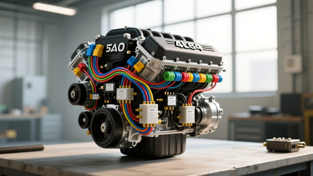
Introduction to Gen III 5.3L and 4L60E Standalone Harnesses
Swapping a GM 5.3L Vortec (LM7, L59, or LM4) paired with a 4L60E transmission into a classic muscle car, 4x4, or custom chassis is one of the most popular powertrain combinations in the aftermarket. However, integrating a modern speed-density engine management system into a vintage or non-GM chassis requires a dedicated stand alone wiring harness for 5.3 with 4L60E. Unlike factory harnesses that rely on a complex BCM (Body Control Module) and VATS (Vehicle Anti-Theft System) network, a standalone harness strips the wiring down to the bare essentials required for the PCM (Powertrain Control Module) to fire the injectors, spark the coils, and command the transmission shift solenoids.
Even with a high-quality aftermarket standalone harness, installation errors, pin-drag, voltage drop, and electromagnetic interference (EMI) can lead to frustrating drivability issues. This guide provides a step-by-step troubleshooting flow designed specifically for the classic 1999-2006 Gen III 5.3L and 4L60E combination utilizing the ubiquitous 0411 (or 12200411) PCM. We will bypass generic advice and focus on exact pinouts, wire gauges, and voltage thresholds required to diagnose and repair your swap.
Phase 1: Prerequisite Power and Ground Verification
Before chasing sensor codes or replacing shift solenoids, you must verify the foundational power and ground circuits. The 0411 PCM requires multiple redundant 12V feeds and clean grounds to operate the internal microprocessors and high-current drivers. According to the SAE J1128 Low Tension Primary Cable Standard, automotive primary wire must handle specific thermal loads, but voltage drop over long routing distances in custom chassis is a frequent failure point.
Voltage Drop Testing the Main Feeds
Do not simply use a test light to verify power. A test light will illuminate even if a corroded connection is only passing 4 volts under load. You must use a Digital Multimeter (DMM) to perform a voltage drop test.
- Battery 12V (Constant): Verify Red wires at PCM Connector C1 (Blue) Pins 1, 2, 3 and Connector C2 (Red) Pins 1, 2. With the key OFF, measure between the battery positive post and these pins. You should see less than 0.1V drop.
- Ignition 12V (Switched): Verify Pink wires at C1 Pins 57, 58 and C2 Pins 18, 19. With the key ON, measure voltage drop from the ignition switch output to these PCM pins.
- PCM Grounds: Verify Black/White wires at C1 Pins 40, 41 and C2 Pins 40, 41. Measure from the battery negative post to these pins with the key ON and the fuel pump priming. A voltage drop greater than 0.05V indicates a poor chassis ground, which will cause erratic injector pulse widths and phantom sensor codes.
Expert Tip: The main power and ground feeds for the PCM and the 4L60E transmission case connector must be routed using a minimum of 10 AWG or 12 AWG stranded copper wire. Using 16 AWG wire for the main PCM power feed will result in severe voltage drop when the cooling fans and fuel pump relays engage, causing the PCM to reset while driving.
Phase 2: Symptom-Driven Troubleshooting Flows
Flow A: Crank, No-Start Condition
If the 5.3L cranks but fails to fire, the issue lies in the ignition, fuel delivery, or cam/crank correlation circuits. Follow this diagnostic tree:
- Verify Injector Pulse: Connect a noid light to an injector harness connector (typically Gray/Pink for 12V feed, and a PCM-controlled ground pulse on the other wire, often Green/Black or Yellow/Black depending on the cylinder). If the noid light does not flash during cranking, check the 12V feed. If 12V is present, the PCM is not seeing a valid crank signal or VATS is active (ensure the VATS resistor pellet circuit or PCM flash has deleted the anti-theft password).
- Cam/Crank Sensor Correlation: The 5.3L uses a 24x crank reluctor and a 1x cam sensor. If the harness routing places the Cam sensor signal wire (usually Brown) too close to the alternator output or ignition coil power feeds, EMI will corrupt the signal. The PCM requires a clean 5V to 12V square wave. Use an oscilloscope to verify the cam signal is not clipped or noisy.
- Coil Pack Power: Each of the eight individual coils requires a Pink 12V ignition feed and a Black ground. A common standalone harness mistake is daisy-chaining the 12V feed to all eight coils using 16 AWG wire. The simultaneous dwell current of eight LS coils can exceed 40 amps. You must use a dedicated relay with 10 AWG feed wire for the coil pack harness.
Flow B: 4L60E Refuses to Shift Past First Gear
The 4L60E is fully electronically controlled. If the transmission stays in first gear and the speedometer works, the PCM has entered 'limp mode' or is missing critical load data. The most common culprit in a standalone swap is the loss of the 12V ignition feed to the transmission case connector or a missing Throttle Position Sensor (TPS) sweep.
- Transmission Case 12V Feed: The 13-way case connector on the 4L60E requires a dedicated 12V switched ignition feed on Pin E (Pink wire). If this wire is mis-pinned or lacks voltage, the shift solenoids cannot energize. The transmission will default to a fail-safe state (usually 2nd or 3rd gear, but can manifest as no movement or stuck in 1st depending on the exact valve body and manual valve position).
- TPS Signal Verification: The PCM calculates shift points and line pressure based on engine load. Backprobe the TPS signal wire (Dark Blue, C1 Pin 33 on the 0411 PCM). With the key ON, engine OFF, slowly open the throttle. The voltage must sweep smoothly from approximately 0.5V (closed) to 4.5V (WOT). If the voltage jumps or drops out, the PCM will inhibit shifting to protect the transmission clutches from burning up due to low line pressure.
- Shift Solenoid Resistance: Disconnect the 13-way case connector. Measure the resistance between Pin A (Shift Sol A - Green/Black) and Pin M (Ground). It should read between 20 and 30 ohms. Repeat for Pin B (Shift Sol B - Yellow/Black). An open circuit indicates a broken wire inside the transmission pan or a pushed-out pin in your standalone harness connector.
Flow C: Limp Mode and TPS/MAP Rationality Faults
If the engine starts and shifts but runs poorly, surges, or throws P0121 (TPS Performance) or P0106 (MAP Rationality) codes, the issue is almost always a 5-Volt Reference (5V REF) circuit overload or ground offset.
- 5V REF Circuit (Gray Wire): The PCM supplies a precise 5V reference to the TPS, MAP, and pedal position sensors. If the standalone harness has a chafed Gray wire touching the chassis, or if an aftermarket 3-bar MAP sensor is wired incorrectly, it will pull the entire 5V REF circuit down to 2V or 0V. This will cause the engine to flood with fuel and stall.
- Sensor Ground Offset: Sensors rely on a dedicated low-noise ground (Black wire) back to the PCM (C1 Pin 8). Do not ground the MAP or TPS sensors to the engine block. The voltage potential between the engine block and the PCM ground can vary by up to 0.2V under alternator load, which is enough to skew the MAP sensor reading by several kPa, triggering a rationality fault.
Critical 0411 PCM Pinout Reference Chart
When troubleshooting a stand alone wiring harness for 5.3 with 4L60E, having the correct PCM pinout is mandatory. The table below outlines the most critical circuits for the Gen III 0411 PCM.
| PCM Connector / Pin | Wire Color | Circuit Function | Expected Voltage / Spec |
|---|---|---|---|
| C1 (Blue) Pin 1, 2, 3 | Red | Battery 12V (Constant) | 12.2V - 12.6V (Key Off) |
| C1 (Blue) Pin 57, 58 | Pink | Ignition 12V (Switched) | 11.5V+ (Key On/Cranking) |
| C1 (Blue) Pin 33 | Dark Blue | TPS Signal to PCM | 0.5V (Idle) to 4.5V (WOT) |
| C1 (Blue) Pin 40, 41 | Black/White | PCM Main Power Ground | < 0.05V Drop to Battery Neg |
| C2 (Red) Pin 18, 19 | Pink | Ignition 12V (Switched) | 11.5V+ (Key On/Cranking) |
| C2 (Red) Pin 83 (Case) | Light Blue | TCC PWM Solenoid Control | PWM Ground Signal (12V base) |
| Trans Case Pin E | Pink | 4L60E Solenoid 12V Feed | 12V (Key On) |
| Trans Case Pin A | Green/Black | Shift Solenoid A Control | 20-30 Ohms Resistance |
Expert Routing and EMI Mitigation
The 5.3L ignition system generates massive amounts of Electromagnetic Interference (EMI). When fabricating or installing your stand alone wiring harness for 5.3 with 4L60E, physical routing is just as critical as electrical continuity. According to guidelines outlined in the Painless Performance LS Harness Installation Manual, high-voltage spark plug wires and low-voltage sensor signal wires must never run parallel to one another.
Always cross high-current and low-current wiring at a strict 90-degree angle. Keep the MAP sensor harness, Cam sensor harness, and Crank sensor harness at least 4 inches away from the alternator output cable and the ignition coil 12V feed wires. If your custom chassis requires the harness to pass near exhaust headers, utilize high-temperature fiberglass sleeving (rated for 1000°F) rather than standard plastic loom, which will melt and cause catastrophic short circuits against the exhaust metal. For deeper diagnostic procedures and multimeter testing techniques, refer to the Haynes Automotive Electrical Troubleshooting Guide to ensure your testing methodology protects the sensitive PCM drivers from accidental shorting during backprobing.
By systematically verifying power feeds, isolating sensor grounds, and respecting the 4L60E's strict voltage requirements, you can transform a frustrating standalone swap into a reliable, street-driven powerhouse.