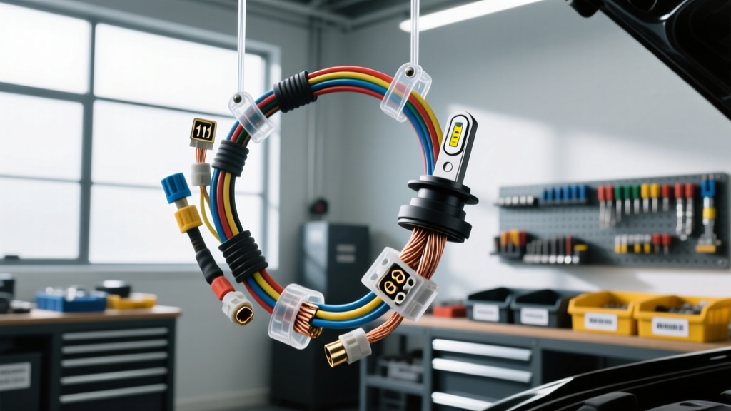
Introduction: The H11 Circuit and Why Harnesses Fail
The H11 bulb is the undisputed standard for modern automotive fog lights and low-beam headlight applications. Utilizing a PGJ19-2 base, the standard halogen H11 draws 55 watts at 12.8 volts, translating to a steady-state current draw of approximately 4.3 amps per bulb. While this seems manageable, the reality of automotive electrical systems involves extreme temperature fluctuations, severe vibration, and massive cold inrush currents. When installing, repairing, or upgrading wiring harnesses h11 fog light setups, technicians and DIYers frequently overlook the physics of the circuit. The result? Melted connector housings, premature bulb failure, and in severe cases, electrical fires.
This guide dissects the most critical safety warnings and common installation mistakes associated with H11 fog light wiring harnesses. By adhering to automotive-grade standards, you can ensure your lighting system operates safely and reliably for the life of the vehicle.
Critical Safety Warnings Before You Cut or Crimp
- Disconnect the Battery: Always disconnect the negative battery terminal before splicing into any OEM lighting circuit. The H11 circuit is often tied directly to the Body Control Module (BCM) or a smart junction box. A short circuit while the battery is connected can instantly fry a $1,200 BCM.
- Beware of Cold Inrush Current: A halogen H11 bulb has a cold filament resistance that is roughly 1/10th of its hot resistance. When first energized, a 4.3A bulb can pull up to 40 amps for a fraction of a second. Your harness wiring, relay contacts, and fuses must be rated to handle this transient spike without tripping or melting.
- Avoid Backprobing OEM Connectors: Never use a T-pin or multimeter probe to backprobe the female H11 PGJ19-2 connector. This spreads the internal tension fingers of the terminal, leading to a loose fit, high resistance, and eventual arcing when the bulb is reinstalled.
The 5 Most Common H11 Fog Light Wiring Harness Mistakes
Mistake 1: Undersizing the Relay Feed Wire (AWG Errors)
Many aftermarket H11 relay harness kits use 16 AWG or even 18 AWG wire for the main battery feed. While 16 AWG wire is technically rated for 10-13 amps in free air, an engine bay is not free air. Bundled inside corrugated loom, subjected to 180°F under-hood temperatures, and stretched over a 12-foot run from the battery to the front bumper, voltage drop becomes a severe issue.
According to the SAE J1128 Low Tension Primary Cable Standard, wire ampacity must be derated for high ambient temperatures. For a dual H11 fog light setup (drawing 8.6A steady state plus inrush), the main battery feed to the ISO relay (Pin 30) and the relay to the split harness (Pin 87) must be a minimum of 12 AWG GXL or TXL wire. Using 18 AWG for the main feed will result in a 1.5V to 2V drop, meaning your 55W H11 bulbs are only receiving 10.8V, drastically reducing their lumen output and altering the beam pattern.
Mistake 2: Bypassing the Relay (Direct Switch Wiring)
A dangerous and surprisingly common mistake is wiring the H11 fog lights directly to the dashboard toggle switch or the OEM headlight switch trigger wire. OEM dashboard switches and clock-spring circuits are typically built with 20 AWG or 22 AWG traces rated for a maximum of 3 to 5 amps. Routing the full 8.6A+ load of dual H11 fog lights through the dash switch will overheat the switch internals, melt the plastic housing, and potentially cause a dash fire.
The Fix: Always use a standard Bosch-style ISO mini relay. The dash switch should only carry the low-amperage trigger signal (under 100mA) to Pin 86 of the relay, while the heavy current flows directly from the battery through the relay to the harness.
Mistake 3: Ignoring the PGJ19-2 Connector Locking Tab and Seals
The H11 PGJ19-2 connector relies on a precise plastic locking tang and a silicone weather-pack seal to keep moisture out. When fabricating custom pigtails or repairing a melted harness, technicians often forget to slide the silicone seal onto the wire before crimping the terminal. Forcing the seal over a crimped terminal tears the silicone, destroying its IP67 waterproof rating. Furthermore, failing to ensure the terminal locking tang clicks securely into the plastic housing allows the terminal to back out slightly. This creates an air gap, leading to micro-arcing, which generates intense localized heat and melts the H11 connector.
Mistake 4: Poor Grounding Practices (The Voltage Drop Trap)
Fog lights are mounted low on the bumper, an area constantly bombarded with road salt, water, and debris. A common mistake is grounding the H11 harness to a random, painted bumper bracket or daisy-chaining the ground with other accessories. A poor ground introduces resistance into the circuit. Since $Power = Current^2 imes Resistance$, even 1 ohm of ground resistance will generate heat and rob the bulbs of voltage.
The Fix: Use a dedicated 12 AWG ground wire with a closed-ring terminal. Scrape the chassis down to bare, shiny metal. Apply a star washer to bite through any microscopic surface corrosion, torque the bolt to the manufacturer's specification (typically 8-10 Nm for M6 bolts), and coat the terminal in dielectric grease to prevent galvanic corrosion.
Mistake 5: Using the Wrong Crimp Terminals
Soldering or using cheap, closed-barrel crimp connectors with heat shrink on the engine side of the H11 harness is a frequent failure point. Solder wicks up into the wire strands under capillary action, creating a rigid section of wire. The extreme vibration of the front bumper and engine bay will cause this rigid solder joint to fatigue and snap. Always use open-barrel, automotive-grade F-crimps or U-crimps applied with a precision ratcheting crimp die. Reference TE Connectivity Automotive Connector Specifications for proper terminal mating geometries.
H11 Fog Light Harness Troubleshooting Matrix
When diagnosing an existing H11 fog light wiring harness, use this symptom-cause-fix matrix to quickly isolate the electrical fault.
| Symptom | Root Cause | Harness / Wiring Fix |
|---|---|---|
| Connector plastic is melted / brown | High resistance at terminal interface causing thermal runaway. | Cut off damaged pigtail. Replace with new PGJ19-2 housing and fresh terminals using a ratcheting crimper. |
| Bulbs glow dimly or flicker at idle | Severe voltage drop due to undersized wire or corroded ground. | Upgrade relay feed to 12 AWG TXL. Clean chassis ground point and apply dielectric grease. |
| Fog lights stay on when switch is off | Relay installed backward (Pins 85/86 swapped with diode protection) or short to power. | Verify ISO relay pinout. Ensure Pin 86 (Trigger) is not spliced into a constant 12V+ source. |
| Bulbs blow out prematurely (weeks) | Voltage spikes or poor harness grounding causing alternator ripple to hit the filament. | Check alternator AC ripple. Ensure harness ground is dedicated and not shared with high-draw components like cooling fans. |
| Water inside the H11 connector | Missing silicone cavity plug on unused harness legs or torn weather seal. | Install OEM-style silicone cavity plugs on any empty relay block slots. Replace torn PGJ19-2 seals. |
Upgrading to LED: Harness Considerations for H11
Many enthusiasts upgrade their H11 halogen fog lights to LED pods or bulbs. While LEDs draw significantly less steady-state current (often 2A to 3A per side), they introduce a new set of harness challenges. Because LEDs lack the natural resistance of a halogen filament, the vehicle's BCM or CAN-bus system may interpret the low current draw as a 'bulb out' error, triggering a dash warning light and cutting power to the circuit via PWM (Pulse Width Modulation) pulsing.
If your H11 harness is tied to a CAN-bus monitored circuit, you must install inline CAN-bus error cancellers (load resistors) or use a harness with an integrated anti-flicker capacitor module. Be warned: load resistors generate massive amounts of heat. They must be mounted to a metal chassis surface using stainless steel hardware, never zip-tied to plastic bumper covers or tucked inside the wiring loom.
Authoritative References & Standards
Proper automotive electrical work requires adherence to established engineering standards. The technical data and safety protocols outlined in this guide are derived from the following industry benchmarks:
- SAE J1128: Low Tension Primary Cable Standard - Defines the thermal, chemical, and mechanical requirements for automotive primary wire, including GXL and TXL insulation types essential for under-hood H11 harness routing.
- TE Connectivity Automotive Connector Specifications - The definitive resource for terminal crimp geometries, weather-pack sealing standards, and PGJ19-2 housing tolerances.
- Hella Technical Guide on Halogen Bulb Specifications - Provides baseline electrical characteristics, inrush current data, and filament resistance metrics for standard 55W H11 applications.
By respecting the physics of the H11 circuit and avoiding these common harness mistakes, you ensure maximum lumen output, complete weatherproofing, and long-term electrical safety for your vehicle's fog light system.