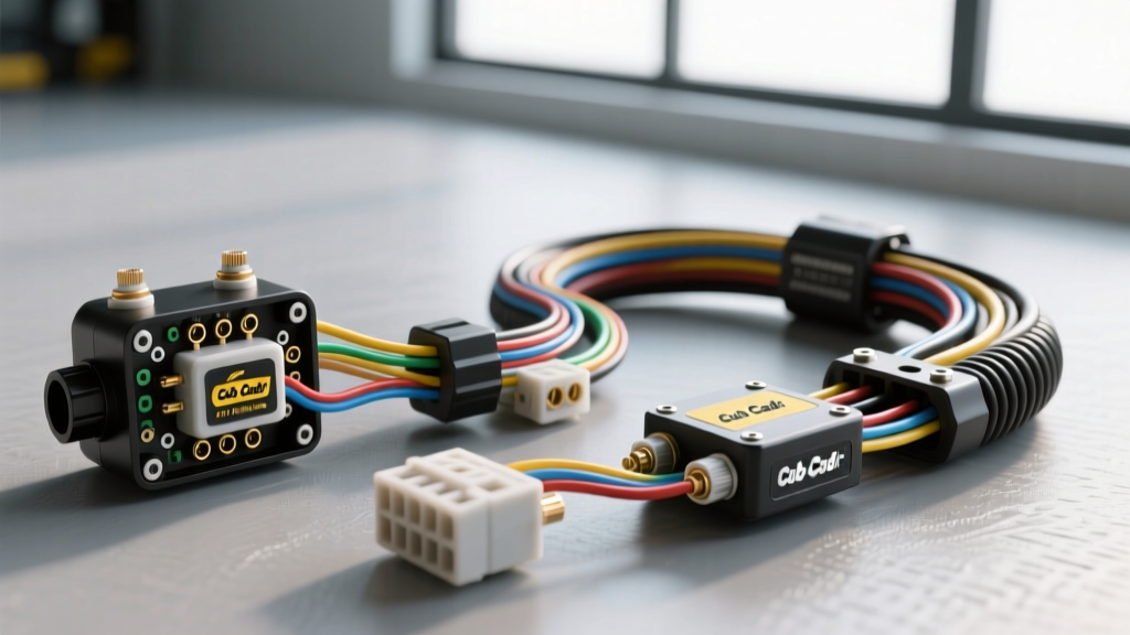
Introduction to the Cub Cadet Wiring Harness Ecosystem
When diagnosing electrical faults in outdoor power equipment, understanding the complete circuit path is critical. The Cub Cadet wiring harness on modern XT1 and XT2 Enduro series lawn tractors represents a sophisticated split-architecture system. Unlike simple point-to-point wiring found on older models, modern MTD-manufactured chassis harnesses integrate a centralized Safety Interlock Module (SIM), heavy-duty PTO clutch relays, and dedicated stator rectification circuits. This comprehensive walkthrough dissects the OEM Cub Cadet wiring harness, providing exact wire color codes, AWG specifications, and connector pinouts required for advanced troubleshooting and custom fabrication.
Core Harness Routing and Connector Pinouts
The main chassis harness originates at the 12V battery, routing a primary 12 AWG red feed through a 30-amp main fuse directly to the ignition switch. From the ignition switch, the harness branches into three distinct sub-circuits: the starter engagement loop, the accessory/lighting loop, and the magneto kill loop. All primary connections utilize sealed AMP Superseal or Weather-Pack connectors to prevent moisture ingress, a common failure point in outdoor power equipment.
Ignition Switch Pinout Specification
The standard 5-pin ignition switch used in the XT1/XT2 series acts as the central logic gate for the tractor. Below is the exact pinout configuration based on SAE J1128 low-tension primary cable standards.
| Pin ID | Function | Wire Color | AWG Size | Destination |
|---|---|---|---|---|
| B (Bat) | Battery Feed | Red | 12 AWG | Main Fuse / Solenoid |
| S (Start) | Starter Signal | Yellow/Red | 14 AWG | Starter Solenoid 'S' Terminal |
| M (Mag) | Magneto Kill | Black | 16 AWG | Safety Interlock Module (SIM) |
| G (Gnd) | Switch Ground | Black | 16 AWG | Chassis Ground Bus |
| L (Light) | Accessory Power | Purple | 14 AWG | Headlights / Dash Illumination |
The Safety Interlock Module (SIM) Circuit
The Safety Interlock Module is the brain of the Cub Cadet harness safety logic. It monitors the status of the brake pedal switch, the PTO engagement switch, and the seat occupancy switch. If the operator leaves the seat while the PTO is engaged, or if the transmission is placed in gear without the brake depressed, the SIM immediately grounds the 'M' (Magneto) pin on the ignition switch, killing the engine spark.
The SIM harness utilizes 16 AWG wires to handle the low-current logic signals. The seat switch is a Normally Closed (NC) circuit; when the operator sits, the switch opens, breaking the ground path to the SIM. The brake switch is a dual-pole Normally Open (NO) / Normally Closed (NC) switch. When the brake is depressed, the NO contacts close to signal the SIM that it is safe to crank the starter. Diagnosing SIM issues requires a digital multimeter (DMM) set to continuity mode to verify the logic states at the .093-inch Molex-style connector pins.
PTO Clutch Harness and Relay Diagnostics
The electromagnetic PTO clutch on a Cub Cadet XT1 typically draws between 3.5 and 4.5 amps at 12V DC. Routing this continuous load through the dashboard PTO switch would cause the 16 AWG dash wires to overheat and melt. To prevent this, the Cub Cadet wiring harness employs a standard 30A automotive ISO relay.
- Pin 86 (Coil +): Receives 12V from the dash PTO switch via a 14 AWG Green wire.
- Pin 85 (Coil -): Grounded to the chassis via a 16 AWG Black wire.
- Pin 30 (Load In): Receives constant 12V from the battery bus via a 12 AWG Red wire, protected by an inline 20A ATO fuse.
- Pin 87 (Load Out): Sends 12V to the PTO clutch coil via a 12 AWG Orange wire terminating in a 2-pin Weather-Pack connector.
Expert Troubleshooting Tip: If the PTO clutch fails to engage, do not immediately replace the clutch. Perform a voltage drop test across the relay. With the PTO engaged, measure the DC voltage between Pin 30 and the clutch connector terminal. A reading higher than 0.2V indicates high resistance in the harness, usually caused by corrosion inside the Weather-Pack connector or a failing relay contact.
Voltage Regulator and Stator Integration
The engine harness on Kohler Courage and Command V-Twin engines interfaces with the main Cub Cadet chassis harness via a 3-pin connector. The stator generates 28V to 35V AC at 3600 RPM. The voltage regulator/rectifier converts this to 14.1V - 14.7V DC to charge the battery and power the 12V accessories.
The 3-pin connector features two outer pins for the AC stator inputs (typically 14 AWG Yellow wires) and a center pin for the DC ground/battery sense (12 AWG Red or White wire). A common failure mode in the Cub Cadet wiring harness is the chafing of these Yellow stator wires against the engine cooling tin, leading to a dead short that destroys the voltage regulator. Always inspect the harness loom where it crosses the engine valley pan.
Common Harness Failure Modes and Multimeter Testing
Outdoor power equipment is subjected to severe vibration, moisture, and thermal cycling. Based on Kohler service documentation and field diagnostics, here are the most prevalent failure modes in the Cub Cadet harness and how to test them:
- Steering Column Chafing: The main harness zip-ties to the steering support tube. Over time, vibration wears through the PVC loom and wire insulation, causing the 12 AWG Red battery feed to short against the steel column. Fix: Inspect the lower column, apply friction tape, and install split-loom conduit.
- Battery Terminal Voltage Drop: The 12 AWG ring terminals connecting the harness to the battery posts often suffer from galvanic corrosion. Test: Set your DMM to DC millivolts. Place the red probe on the battery post and the black probe on the harness ring terminal while cranking. A reading above 50mV indicates the terminal must be cut off and replaced with a new adhesive-lined heat-shrink crimp.
- Seat Switch Connector Moisture: The 2-pin connector under the seat is exposed to rain and wash-water. Fix: Disconnect the connector, clean the brass pins with electrical contact cleaner, and pack the female terminal cavity with dielectric grease to displace moisture.
Harness Repair and Fabrication Standards
When repairing a damaged section of the Cub Cadet wiring harness, never use electrical tape or twist-on wire nuts. Automotive-grade harness repair requires adhesive-lined marine heat shrink and a ratcheting crimp tool. For 12 AWG to 14 AWG wires, use a #12-10 AWG butt connector with a dual-wall heat shrink ratio of 3:1. When applying heat, start from the center and work outward to ensure the internal sealant melts and extrudes slightly from the ends, creating a completely waterproof barrier against the elements.
By understanding the specific wire gauges, relay logic, and safety interlock pathways detailed in this walkthrough, technicians and DIY enthusiasts can accurately diagnose and repair the Cub Cadet wiring harness, ensuring reliable starting and safe operation for years to come.