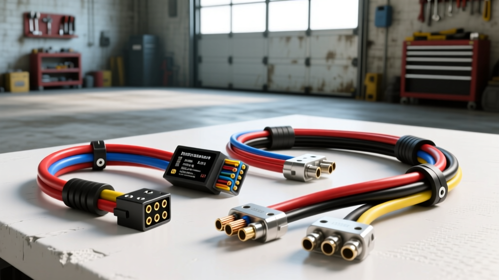
Why a Dedicated Rock Light Wiring Harness Matters
Upgrading your off-road vehicle with underbody illumination requires more than just mounting LED pods and twisting wires together. The harsh environments these lights operate in—exposed to water, mud, vibration, and extreme temperature fluctuations—demand a purpose-built rock light wiring harness. A poorly designed or undersized universal harness will inevitably lead to voltage drop, flickering, melted insulation, or complete electrical failure when navigating water crossings. Selecting the right harness kit involves comparing wire gauges, environmental sealing ratings, relay configurations, and connector types to ensure your auxiliary lighting system performs reliably on the trail.
Calculating Amperage and AWG Requirements
The foundation of any lighting harness is selecting the correct American Wire Gauge (AWG) based on the total amperage draw and the length of the wire run. Most modern LED rock light pods draw between 0.8A and 1.5A each. If you are running an 8-pod kit drawing 1.2A per pod, your total continuous load is 9.6A. According to SAE J1128 standards for low-tension primary automotive cables, using 18 AWG wire for a 15-foot run at 10A will result in a voltage drop of nearly 0.8V, starving the LEDs and causing premature driver failure.
For optimal performance, the main power feed from the battery to the relay, and from the relay to the first branch splitter, must be 14 AWG or 12 AWG copper. The branch lines splitting off to individual pods can safely step down to 16 AWG, provided the individual runs do not exceed 6 feet. Always calculate your fuse size at 125% of the maximum continuous draw; for a 9.6A system, a 15A ATO or Mini-ATO blade fuse is the correct specification.
Harness Configuration Comparison Chart
When comparing off-the-shelf harness kits against custom-fabricated solutions, use the following specification matrix to ensure the kit meets your specific pod count and electrical requirements.
| Kit Configuration | Main Power AWG | Branch AWG | Relay Rating | Inline Fuse | Recommended Connector |
|---|---|---|---|---|---|
| 4-Pod (Up to 6A) | 16 AWG | 18 AWG | 30A ISO Mini | 10A Mini-ATO | 2-Pin Deutsch DT |
| 6-Pod (Up to 10A) | 14 AWG | 16 AWG | 40A ISO Mini | 15A ATO | 2-Pin Deutsch DT |
| 8-Pod (Up to 15A) | 12 AWG | 14 AWG | 40A ISO Mini | 20A ATO | 2-Pin / 4-Pin DT |
Connector Selection: Environmental Sealing and Vibration Resistance
The most common failure point in any rock light wiring harness is the connection between the main harness and the individual LED pods. Bullet connectors and heat-shrink butt splices are entirely unacceptable for underbody applications due to capillary action drawing moisture into the crimp barrel, leading to galvanic corrosion.
Premium harness kits utilize sealed automotive connectors. The industry gold standard is the TE Connectivity Deutsch DT series. These connectors feature an IP68 waterproof rating, capable of withstanding continuous submersion in water crossings. They utilize solid copper pins (Size 16) crimped with a specialized open-barrel tool, backed by silicone rear seals and hard plastic wedge locks that prevent the pins from backing out under heavy chassis vibration. An alternative is the AMP Superseal 1.5 series, which offers IP67 protection and is slightly more compact, making it ideal for tight clearance areas near the axle differentials, though it is marginally less resistant to extreme physical abrasion than the Deutsch DT.
Relay Logic and Modern Vehicle PWM Alternators
Every robust rock light harness must utilize a relay to isolate the high-current load from the vehicle's interior switchgear. A standard Bosch-style ISO mini 4-pin relay is the most reliable choice. The pinout configuration is standardized across the industry:
- Pin 30: 12V+ constant power from the battery (via inline fuse).
- Pin 85: Chassis ground.
- Pin 86: 12V+ trigger signal from the interior switch or auxiliary control module.
- Pin 87: 12V+ output to the rock light load.
Critical Compatibility Note: Modern trucks (2015+ GM, FCA/Stellantis, and Ford models) utilize smart, Pulse Width Modulated (PWM) alternators and body control modules (BCM) that monitor parasitic draw. If you trigger Pin 86 directly from a factory upfitter switch or tap into a factory lighting circuit, the BCM may detect an unexpected voltage variance and pulse the ground, causing your rock lights to strobe or flicker. To resolve this, high-end harness kits include an integrated anti-flicker capacitor or a CAN-bus isolation module to smooth the trigger signal before it reaches the relay coil.
Wire Routing, Loom, and SAE Standards
Routing a harness beneath a vehicle requires careful attention to abrasion and heat. Avoid routing wires near exhaust components or steering shafts. When securing the harness to the frame, use nylon P-clips or aluminum adel clamps with rubber cushions rather than standard zip-ties, which can saw through wire insulation over time due to chassis flex.
For wire loom, avoid rigid split-loom tubing in underbody applications; it traps water, mud, and debris against the wire insulation, accelerating the degradation of PVC jackets. Instead, select harness kits that utilize PET (Polyethylene Terephthalate) expandable braided sleeving. PET sleeving is highly abrasion-resistant, allows water to drain freely, and resists mold and mildew buildup. Furthermore, ensure the wire insulation itself meets automotive OEM specifications for cross-linked polyethylene (XLPE), which can withstand engine bay and underbody ambient temperatures up to 125°C without melting or becoming brittle in sub-zero conditions.
Troubleshooting Common Harness Failures
Even with a premium harness, installation variables can cause operational issues. Use this diagnostic tree to resolve common rock light wiring problems:
- Symptom: Lights flicker rapidly at idle but stabilize at higher RPMs.
Cause: The vehicle's smart alternator is in low-output mode, or the trigger signal from Pin 86 is receiving pulsed voltage.
Fix: Install a 4700µF electrolytic capacitor in parallel with the relay coil (between Pins 85 and 86) to smooth the voltage, or use a dedicated PWM filter module. - Symptom: Pods on the passenger side are noticeably dimmer than the driver side.
Cause: Excessive voltage drop due to undersized branch wires or a daisy-chain topology instead of a star/hub topology.
Fix: Rewire the harness using a central distribution hub, ensuring equal length and adequate AWG (14 AWG minimum) for all branch runs. - Symptom: Inline fuse blows immediately upon switching the lights on.
Cause: A pinched wire shorting to the chassis, or water ingress inside a poorly crimped Deutsch connector causing a dead short.
Fix: Disconnect the load at Pin 87. If the relay clicks and the fuse holds, the short is downstream. Inspect all branch splitters and crimp terminals for exposed copper strands bridging the positive and negative circuits.
Final Selection Verdict
When purchasing a rock light wiring harness kit, prioritize those that explicitly state the use of pure oxygen-free copper (OFC) rather than copper-clad aluminum (CCA), as CCA wire suffers from higher resistance and is prone to snapping under vibration. Ensure the kit includes a weather-pack relay socket with sealed pigtail wires, and demand Deutsch DT connectors for all modular connections. By matching the AWG to your specific amperage draw and respecting the environmental demands of off-road use, your lighting system will deliver consistent, brilliant illumination for the life of the vehicle.