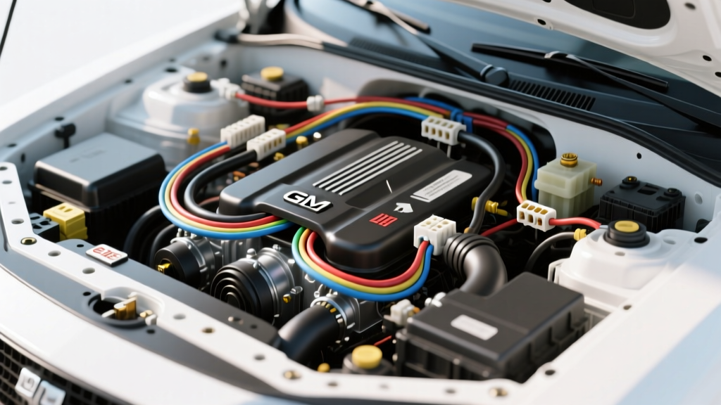
Introduction to Harness Routing and Length Calculations
When fabricating, modifying, or replacing an automotive electrical system, guessing wire lengths is a primary cause of premature harness failure. Determining the standard cable lengths for wiring harnesses requires more than just measuring the physical distance between two components. It demands a thorough understanding of engine dynamics, thermal expansion, and industry routing tolerances. According to SAE J1128 (Low Tension Primary Cable) standards, automotive wire must be routed to accommodate engine roll, suspension articulation, and heat cycling without placing mechanical tension on terminal crimps.
In this complete wiring diagram walkthrough, we will dissect a GM LS1 engine harness. We will calculate the exact standard cable lengths required for critical sub-circuits, detail the necessary service and drip loops, and provide the specific AWG ratings, wire color codes, and Delphi connector pinouts required for a factory-grade installation.
Complete Wiring Diagram Walkthrough: GM LS1 Engine Harness
The GM LS1 (Generation III) engine utilizes a centralized Powertrain Control Module (PCM), typically PN 12200411, featuring two 80-way connectors: a Blue connector (primarily sensors and low-side drivers) and a Red connector (primarily injectors, coils, and high-current outputs). Routing a harness from the PCM, located in the passenger side cabin or fender well, to the engine bay requires precise length calculations to avoid chafing against the firewall or stretching during engine torque roll.
Section 1: ECM to Injector and Coil Sub-Harness
The fuel injector circuit relies on a switched 12V power supply and a PCM-controlled ground. For Cylinder 1, the 12V feed is typically a Pink/Black wire, while the PCM ground control is Dark Green. These circuits utilize 18 AWG TXL (Cross-linked Polyethylene) wire, chosen for its thin insulation wall and high-temperature resistance (up to 125°C continuous).
The physical distance from the PCM firewall grommet to the front fuel rail injector is roughly 38 inches. However, the standard cable length for wiring harnesses in this circuit must be 56 inches. This additional 18 inches accounts for a 6-inch service loop at the PCM connector (to allow for bench servicing without unplugging), 8 inches of routing through a 1-inch firewall grommet, and a 4-inch drip loop immediately before the Metri-Pack 150 injector connector to prevent moisture wicking into the terminal cavity.
Section 2: Sensor Routing and Drip Loops
Low-voltage analog sensors, such as the Mass Air Flow (MAF) and Throttle Position Sensor (TPS), require strict adherence to length and shielding standards to prevent Electromagnetic Interference (EMI) from adjacent ignition coil wires. The MAF sensor circuit uses five wires: 12V (Red), Ground (Black), Signal (Yellow), Intake Air Temp Signal (Tan), and IAT Ground (Black/White).
These low-current circuits are built using 20 AWG wire. The standard cable length from the PCM to the MAF sensor on a standard F-body LS1 application is 34 inches. This includes a 28-inch base route and a mandatory 6-inch drip loop. Because the MAF is mounted directly to the air intake tube, which moves independently of the engine block during acceleration, the harness must feature an additional 4-inch flexible slack section wrapped in Tesa cloth tape to absorb high-frequency vibrations without transferring stress to the sensor's internal solder joints.
Standard Cable Lengths Specification Chart
The following table outlines the engineered standard lengths for primary LS1 engine harness circuits. These measurements assume a standard passenger-side firewall pass-through and a stock engine configuration.
| Circuit Description | Wire Gauge (AWG) | Insulation Type | Base Route Length | Service/Drip Loop | Total Standard Length | Connector Type |
|---|---|---|---|---|---|---|
| Injector Bank 1 (Cyl 1,3,5,7) | 18 AWG | TXL | 38.0 in | 18.0 in | 56.0 in | Delphi Metri-Pack 150 |
| Injector Bank 2 (Cyl 2,4,6,8) | 18 AWG | TXL | 46.0 in | 18.0 in | 64.0 in | Delphi Metri-Pack 150 |
| Ignition Coil Front (Cyl 1,3) | 16 AWG | TXL | 42.0 in | 14.0 in | 56.0 in | Delphi Metri-Pack 280 |
| MAF Sensor (5-Wire) | 20 AWG | GXL | 28.0 in | 6.0 in | 34.0 in | Delphi Metri-Pack 150 |
| Alternator Main Charge | 8 AWG | SXL | 65.0 in | 12.0 in | 77.0 in | Ring Terminal / M8 Stud |
| Main Engine Ground (Block to Chassis) | 4 AWG | SGT | 24.0 in | 4.0 in | 28.0 in | Ring Terminal / M10 Stud |
Calculating Slack: SAE Standards and Real-World Tolerances
Calculating the correct slack is governed by mechanical design principles outlined in ISO 6722 (Road vehicles — 60 V and 600 V single-core cables) and SAE J1292. A critical rule in harness fabrication is the minimum bend radius. For a bundled harness wrapped in split loom, the minimum bend radius must be at least three times the outer diameter of the bundle. If a 1-inch diameter harness bundle is forced into a 1-inch radius turn at the firewall, the wires on the outside of the bend will stretch, while the wires on the inside will compress, leading to insulation failure and terminal back-out.
Furthermore, standard cable lengths must account for the "Service Loop." A service loop is an intentional, neatly coiled excess of wire (typically 4 to 8 inches) secured with a zip tie or Tesa tape near a major connector (like the PCM). This allows a technician to unplug the connector and pull it onto a workbench for diagnostic probing without having to remove the entire harness from the vehicle's chassis clips.
Expert Troubleshooting: When Standard Lengths Cause Failures
Deviating from standard cable lengths introduces severe reliability risks. If a harness is built too short, the engine's torque roll (which can shift the powertrain up to 3/4 of an inch under heavy load) will place direct tensile stress on the connector cavities.
Failure Mode 1: Fretting Corrosion in Metri-Pack Connectors
When standard lengths are ignored and wires are pulled taut, the micro-vibrations of the engine cause the male and female terminals inside Delphi Metri-Pack 150 and 280 connectors to rub against each other. This friction wears away the tin or silver plating, exposing the base brass to oxygen and moisture. The resulting fretting corrosion increases circuit resistance, leading to erratic injector pulse widths and random misfire codes (e.g., P0300).
Failure Mode 2: Voltage Drop in High-Current Circuits
If an aftermarket alternator is relocated, and the standard 77-inch length for the main charge wire is exceeded to 110 inches without upsizing the wire gauge, voltage drop becomes a critical issue. An 8 AWG wire carrying 100 Amps over 77 inches will exhibit a voltage drop of approximately 0.35V. Extending that same 8 AWG wire to 110 inches increases the drop to 0.50V or more, which can cause the PCM to undercharge the battery or trigger a P0562 (System Voltage Low) code. Always consult voltage drop charts and upsize to 4 AWG or 2 AWG when standard lengths must be exceeded for custom alternator bracket setups.
Mitigation Strategies for Custom Lengths
- Use Tesa Cloth Tape: Never use standard vinyl electrical tape in the engine bay. Heat causes the adhesive to melt and the vinyl to unravel. Use Tesa 51036 PET cloth tape, which withstands 150°C and provides excellent abrasion resistance.
- Strain Relief at Grommets: When passing through the firewall, the harness should be secured on both sides of the grommet. The grommet itself should bear the mechanical load of the harness weight, not the wire terminals.
- Terminal Seating Verification: After crimping and inserting terminals into the connector housing, always perform a "pull test." Tug gently on the wire (not to exceed 10 lbs of force) to ensure the terminal's locking tang has fully engaged the plastic housing.
- Dielectric Grease Application: Apply a small amount of silicone dielectric grease to the connector seal (not directly on the metal terminals) to prevent moisture ingress and lubricate the rubber seal during mating, as recommended by Aptiv (formerly Delphi Automotive) connection system guidelines.
By strictly adhering to engineered standard cable lengths, incorporating proper drip and service loops, and utilizing automotive-grade TXL wiring and sealed connectors, you ensure the electrical system will survive the harsh under-hood environment for the life of the vehicle.