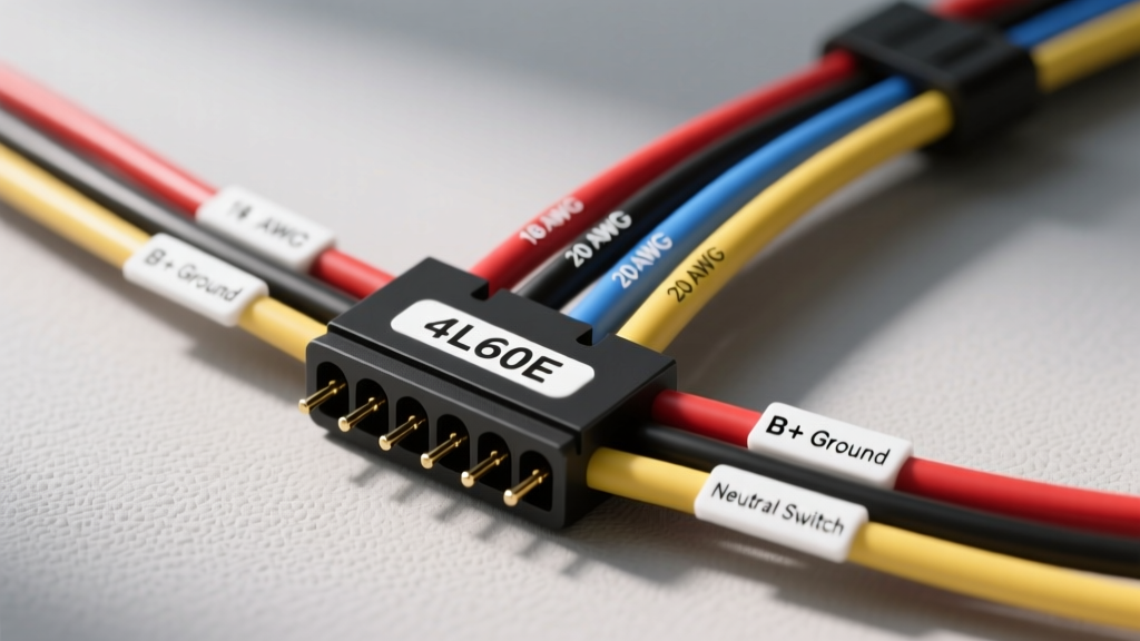
Architecture of the 4L60E Internal and External Harness
The GM 4L60E (and its evolutionary successors, the 4L65E and 4L70E) relies on a sophisticated network of pulse-width modulated (PWM) solenoids, on/off shift solenoids, and permanent magnet generators (PMGs) to execute precise hydraulic shifts. Understanding the wiring harness for 4L60E transmission applications requires dividing the system into two distinct zones: the internal harness and the external harness.
The internal harness is fully submerged in automatic transmission fluid (ATF) and operates in a high-heat, high-vibration environment. It routes from the 13-way case connector to the valve body solenoids, the Transmission Fluid Pressure (TFP) switch manifold, and the internal speed sensors (on select late-model applications). The external harness bridges the 13-way case connector to the Powertrain Control Module (PCM) or standalone transmission controller, navigating the engine bay and undercarriage. When building a custom harness, adapting an engine swap, or diagnosing a shift fault, referencing the exact pinout, wire gauge, and insulation requirements is critical to prevent catastrophic transmission failure.
13-Way Case Connector Pinout Reference (1998-2006 PWM)
The following table details the standard 13-way case connector pinout for the widely deployed 1998-2006 PWM-equipped 4L60E. Note that Pin 'I' is intentionally skipped in GM automotive connectors to prevent confusion with the numeral '1'.
| Pin | Circuit Designation | Typical OEM Wire Color | Function & Specifications |
|---|---|---|---|
| A | TCC PWM Solenoid | Yellow / Black Tracer | Torque Converter Clutch Pulse Width Modulation control. Low-side driver. |
| B | 1-2 Shift Solenoid (SS1) | Light Blue | Controls 1st to 2nd gear upshifts and downshifts. Normally Closed (NC). |
| C | 2-3 Shift Solenoid (SS2) | Dark Blue | Controls 2nd to 3rd gear upshifts and downshifts. Normally Closed (NC). |
| D | 3-2 Shift Solenoid | Brown | Provides engine braking and kickdown control for 3rd to 2nd gear. Normally Open (NO). |
| E | TFP Switch Signal | White | Transmission Fluid Pressure switch multiplexed signal to PCM. |
| F | TFP Switch Ground | Black | Dedicated ground for the pressure switch manifold. |
| G | Solenoid Ground | Black | Common low-side ground return for all shift and TCC solenoids. |
| H | Sensor Ground | Black / White Tracer | Low reference ground for ISS and OSS sensors. |
| J | ISS Signal | Yellow | Input Speed Sensor (Turbine shaft) AC signal. |
| K | OSS Signal | Purple | Output Speed Sensor (Output shaft) AC signal. |
| L | ISS Low Reference | Yellow / Black Tracer | Input Speed Sensor shield and low reference return. |
| M | OSS Low Reference | Purple / White Tracer | Output Speed Sensor shield and low reference return. |
| N | Shield Ground | Bare / Shield Drain | External braided shield drain wire for EMI/RFI noise reduction. |
Solenoid Circuit Specifications and Wire Gauge Requirements
When fabricating or repairing a wiring harness for 4L60E transmission applications, selecting the correct wire gauge and insulation type is non-negotiable. The internal environment of the transmission pan routinely exceeds 180°F (82°C) and is saturated with petroleum-based ATF.
Wire Gauge (AWG) and Resistance
- Shift Solenoids (Pins B, C, D): These are simple on/off valves. The OEM internal harness utilizes 20 AWG wire. At 68°F (20°C), expect a resistance reading of 19 to 24 ohms. If your multimeter reads below 15 ohms, the solenoid coil is shorting; if it reads infinite (OL), the coil or the internal harness crimp has failed.
- TCC PWM Solenoid (Pin A): The Torque Converter Clutch solenoid requires a variable duty cycle signal to smoothly apply the converter clutch. It operates at a lower resistance, typically 10 to 11 ohms at 68°F, and requires a robust 20 AWG or 18 AWG wire to handle the higher amperage draw during peak PWM duty cycles.
- External Harness Routing: For the external engine bay harness, step up to 18 AWG for all signal and solenoid control wires to account for voltage drop over longer runs. Power and ground feeds for standalone controllers should utilize 14 AWG or 12 AWG wire.
Insulation Material Standards
Standard PVC (Polyvinyl Chloride) wire insulation will absorb ATF, swell, and eventually crack, leading to short circuits against the transmission pan or valve body. According to SAE J1128 standards for automotive wire, you must use XLPE (Cross-Linked Polyethylene) or Tefzel (PTFE) insulated wire for any harness segment submerged in transmission fluid. These materials are rated for continuous 150°C operation and are chemically inert to Dexron III, Dexron VI, and synthetic ATF blends.
Transmission Fluid Pressure (TFP) Switch Integration
The TFP switch manifold is a critical component mounted directly to the valve body. It contains six individual pressure switches (D4, D3, D2, D1, R, and P/N) that inform the PCM of the current gear state based on hydraulic line pressure. The internal harness routes these signals to Pin E and Pin F. A common failure mode in high-mileage 4L60E units is the degradation of the internal harness connector that plugs into the TFP switch. The plastic locking tang becomes brittle from heat cycling, causing the connector to vibrate loose. This results in erratic line pressure, harsh shifts, and DTC P1810 (TFP Valve Position Switch Circuit). When replacing the internal harness, always secure the TFP connector with a high-temperature silicone adhesive or a mechanical zip-tie wrap to the valve body bracket.
External Harness Routing and Standalone Adapter Kits
For LS swap applications or custom vehicle builds utilizing a standalone transmission controller (such as the TCI EZ-TCU, Holley Terminator, or MicroSquid), an adapter harness is required. These kits bridge the GM 13-way case connector to the specific ECU pinout.
When routing the external harness, avoid running the ISS and OSS sensor wires parallel to ignition coil packs, fuel injector harnesses, or alternator power cables. The ISS and OSS are permanent magnet generators that output a low-voltage AC sine wave (typically 1.5V to 40V AC depending on RPM). Electromagnetic Interference (EMI) from ignition systems will corrupt the AC signal, causing the PCM to miscalculate slip RPM and trigger harsh TCC apply or shift flares. Always use twisted pair wiring for the ISS and OSS circuits, and terminate the shield drain wire (Pin N) at the PCM/TCM ground reference point only—never ground the shield at both ends, as this creates a ground loop.
Diagnostic Decision Tree: Harness-Related Shift Faults
Use the following symptom-cause-fix decision tree to isolate wiring harness faults before condemning internal mechanical components.
Symptom: Harsh 1-2 Shift, No Engine Braking in Manual 2
- Cause: 3-2 Shift Solenoid circuit open or shorted to ground.
- Diagnostic Step: Check continuity between PCM connector and Case Connector Pin D. Inspect the internal harness crimp at the 3-2 solenoid pigtail.
- Fix: Repair external harness chafing near the exhaust crossover, or replace the internal valve body harness if the open is internal.
Symptom: TCC Slip, DTC P1870 (Transmission Component Slipping)
- Cause: TCC PWM Solenoid wire broken inside the insulation, or degraded PWM solenoid coil.
- Diagnostic Step: Measure resistance at Case Connector Pin A to Pin G. If resistance fluctuates while wiggling the internal harness, the wire is fractured at the crimp.
- Fix: Replace the internal harness assembly and verify the TCC PWM solenoid screens are clear of debris.
Symptom: Speedometer Drops Out, Shift Flares at High MPH
- Cause: OSS (Output Speed Sensor) signal shorted or shield compromised.
- Diagnostic Step: Check OSS resistance (typically 1400-2400 ohms). Inspect the external harness where it passes near the transfer case adapter or crossmember for physical chafing.
- Fix: Repair the twisted pair wiring and apply split-loom corrugated tubing with Tesa 51036 high-temp harness tape.
Installation, Torque Specs, and Heat Shielding
When installing a new internal wiring harness for 4L60E transmission rebuilds, the valve body must be removed. The internal harness is sandwiched between the valve body separator plate and the case. Ensure no wires are pinched between the separator plate and the valve body casting. When reinstalling the valve body, the retaining bolts must be torqued to 10 Nm (88 lb-in) in the sequence specified by GM Service Information. Over-torquing will warp the valve body casting, causing cross-leaks and solenoid binding.
For the external case connector, apply a small amount of dielectric grease to the 13-way pins to prevent moisture intrusion and galvanic corrosion. Finally, if your vehicle features a tight exhaust clearance near the passenger side transmission pan, install an aluminized fiberglass heat shield sleeve over the external harness loom to prevent radiant heat from melting the corrugated split-loom and degrading the wire insulation over time. For further rebuilding standards and electrical diagnostic procedures, consult the Automatic Transmission Rebuilders Association (ATRA) technical bulletins.