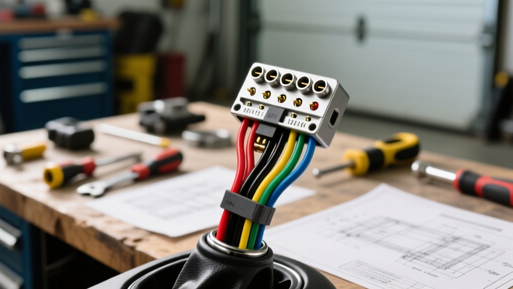
The Anatomy of a Steering Column Wiring Harness Upgrade
Upgrading a classic muscle car or truck with a modern tilt steering column is one of the most impactful modifications you can perform. Whether you are swapping a worn-out Saginaw column for an aftermarket ididit unit or adapting a late-model GM column into a resto-mod chassis, the steering column wiring harness serves as the central nervous system for your vehicle's lighting, safety, and accessory circuits. A poorly integrated column harness will result in backfed circuits, melted bulkhead connectors, and critical lighting failures.
In this technical guide, we break down the exact wire color codes, AWG specifications, and integration strategies required to seamlessly mate a replacement steering column wiring harness to your vehicle's main chassis loom. We will cover both the legendary GM 9-pin turn signal matrix and the integration challenges presented by modern clock-spring equipped columns.
Decoding the Classic GM 9-Pin Turn Signal Connector
The vast majority of classic GM vehicles (1969-1990s) utilize a standardized 8-pin/9-pin turn signal switch pigtail, often housed in a Packard 56-Series connector shell. When upgrading your column, you will likely need to splice this pigtail into an aftermarket chassis harness (such as a Painless Performance or American Autowire kit). Understanding the internal switching matrix of the hazard and turn signal stalk is critical to avoid cross-circuiting.
| Cavity | Wire Color | Function | AWG | Switch Logic |
|---|---|---|---|---|
| A | White | Brake Light Switch Feed | 14 AWG | Interrupted by turn signal stalk during left/right actuation to allow turn signals to override brake lights. |
| B | Black | Horn Relay Ground | 16 AWG | Provides a ground path to the horn relay coil when the steering wheel horn button is depressed. |
| C | Purple | Turn Signal Flasher Feed | 14 AWG | 12V pulsed power from the turn signal flasher module. |
| D | Brown | Hazard Flasher Feed | 14 AWG | 12V pulsed power from the hazard flasher module (bypasses turn signal switch). |
| E | Dark Blue | Right Front Turn Signal | 14 AWG | Routed to RF parking/turn bulb. |
| F | Light Green | Right Rear Turn/Brake | 14 AWG | Combines brake and right turn signal at the rear bulb filament. |
| G | Yellow | Left Rear Turn/Brake | 14 AWG | Combines brake and left turn signal at the rear bulb filament. |
| H | Dark Green | Left Front Turn Signal | 14 AWG | Routed to LF parking/turn bulb. |
The Hazard and Turn Signal Matrix Explained
A common failure mode during a steering column wiring harness upgrade is the 'hyper-flash' or the failure of brake lights to disengage when a turn signal is activated. This occurs because the GM turn signal switch physically disconnects the White (Brake Feed) wire from the corresponding rear circuit (Yellow or Light Green) and replaces it with the pulsed Purple (Turn Flasher) feed. If your aftermarket harness uses independent brake and turn signal bulbs (European style), you must install a tail light converter module before the harness reaches the column, as the GM column expects a combined brake/turn rear filament.
Modern Resto-Mod Swaps: Clock Springs and CAN-Bus
If your upgrade project involves adapting a 2010+ Camaro or Corvette steering column into a classic chassis to utilize a modern airbag and steering wheel controls, the wiring complexity increases exponentially. Modern columns utilize a 16-pin or 24-pin Delphi GT 280 connector.
- Clock Spring Grounding: The airbag clock spring requires a dedicated, ultra-low resistance ground path to prevent static discharge from deploying the SRS module. Always route a dedicated 12 AWG ground wire from the column housing directly to the chassis dash ground bus. Never rely on the steering shaft bearings for SRS grounding.
- CAN-Bus Integration: Modern columns route steering wheel control (SWC) signals via GMLAN serial data lines. If you are integrating an aftermarket head unit, you will need a CAN-bus interface module (like an Axxess ASWC-1) spliced into the column's data ribbon cable to retain volume and cruise control functions.
Step-by-Step: Splicing and Routing the Column Pigtail
When mating your new steering column wiring harness to the chassis, the physical connection is just as important as the electrical logic. The steering column is subject to high-frequency vibration and extreme temperature cycling.
- Wire Selection: Replace any cheap PVC wire in the replacement pigtail with SAE J1128 GXL or TXL cross-linked polyethylene wire. GXL wire features a thin-wall insulation rated for 125°C, allowing you to bundle multiple 14 AWG wires without exceeding the physical constraints of the column shift tube.
- Terminal Crimping: Do not solder the wires to the Packard 56-Series terminals. Solder wicks up the copper strands, creating a rigid point that will snap under the vibration of the steering shaft. Use an open-barrel crimping tool and seal the connection with dual-wall, adhesive-lined heat shrink.
- Bulkhead Pass-Through: If routing the harness through the firewall, use a dedicated rubber grommet. Apply dielectric grease to the wires before pulling them through the grommet. This prevents the insulation from tearing and stops capillary action from wicking moisture into the copper strands over time.
- Drip Loops: Always form a 'drip loop' in the harness before it enters the firewall or connects to the column. This ensures that any condensation running down the wires drips off the bottom of the loop rather than pooling inside the connector cavity, which leads to copper oxidation and high-resistance voltage drops.
Troubleshooting Decision Tree: Flasher and Brake Light Failures
Even with a meticulous wiring diagram reference like those provided by MAD Enterprises, post-installation gremlins are common. Use this diagnostic tree to isolate column harness faults:
- Symptom: Brake lights stay on permanently, even when the pedal is released.
- Cause: The brake pedal switch plunger is not fully depressing, or the White wire is shorted to 12V upstream of the column.
- Fix: Adjust the pedal stop-switch bracket. Verify continuity between the White wire and ground with the pedal up.
- Symptom: Hazards work perfectly, but turn signals do not illuminate or flash.
- Cause: Loss of 12V on the Purple wire (Turn Flasher feed), or a failed thermal turn signal flasher module.
- Fix: Probe Cavity C (Purple) with a multimeter while the ignition is in the 'Run' position. If 12V is present, replace the flasher can. If you have upgraded to LED bulbs, ensure you have installed an electronic (non-thermal) LED flasher module, as LEDs do not draw enough amperage to trigger a classic bi-metallic thermal flasher.
- Symptom: Right turn signal illuminates the dashboard indicator but the exterior bulb stays solid (no flashing).
- Cause: High resistance on the Dark Blue (RF) wire, or a poor ground at the right front parking lamp housing.
- Fix: Perform a voltage drop test across the Dark Blue wire from the column connector to the lamp socket. A drop greater than 0.2V indicates a corroded bulkhead connector or a failing crimp terminal inside the column pigtail.
Expert Tips for Clean Routing and Strain Relief
When finalizing your steering column wiring harness installation, strain relief is paramount. The column tilt mechanism and telescoping features (if equipped) require the harness to flex every time the driver adjusts the wheel. Secure the harness to the lower column jacket using nylon cable ties, leaving exactly 2 to 3 inches of slack between the tie-down point and the column connector. Wrap the final 12 inches of the loom in Tesa 51036 PET cloth tape. This tape is the OEM standard for Painless Performance and factory harnesses; it prevents the plastic loom from rattling against the steel column tube and provides excellent abrasion resistance against the parking brake pedal linkage.