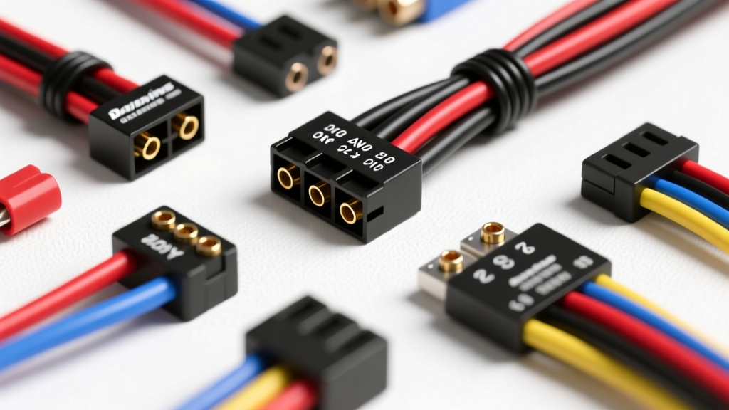
Baja Designs Wiring Harness Architecture Overview
Integrating high-output auxiliary lighting requires a robust electrical distribution network capable of handling sustained high-amperage loads without excessive voltage drop. The standard Baja Designs wiring harness ecosystem is engineered around a centralized Bosch-style relay architecture, utilizing 14 AWG primary conductors and sealed Deutsch DT series connectors. This technical reference details the exact specifications, pinout configurations, and termination protocols required to install, modify, or troubleshoot Baja Designs harness kits for platforms ranging from the Squadron Sport to the LP9 Pro arrays.
Core Conductor Specifications and AWG Ratings
Automotive auxiliary lighting harnesses must adhere to strict voltage drop thresholds. According to SAE J1128 standards for low-tension primary cables, the insulation and copper stranding must withstand engine bay thermal cycles while maintaining conductivity. Baja Designs utilizes Cross-Linked Polyethylene (XLPE) insulated, multi-strand copper wire to ensure flexibility and high-temperature resistance.
Wire Color Codes and Gauge Matrix
| Wire Color | AWG Size | Strand Count | Circuit Function | Max Continuous Ampacity | Insulation Type |
|---|---|---|---|---|---|
| Red | 14 AWG | 41 / 0.254mm | Main 12V+ Battery Feed (Relay Pin 30) | 20A (Chassis routing) | XLPE (125°C) |
| Black | 14 AWG | 41 / 0.254mm | Main Chassis Ground (Relay Pin 87 to Light) | 20A (Chassis routing) | XLPE (125°C) |
| White | 18 AWG | 16 / 0.254mm | Trigger / Switch Signal (Relay Pin 85) | 5A | PVC (105°C) |
| Black (Thin) | 18 AWG | 16 / 0.254mm | Relay Coil Ground (Relay Pin 86) | 5A | PVC (105°C) |
Technical Note on Voltage Drop: A standard 14 AWG copper wire exhibits a resistance of approximately 2.525 milliohms per foot at 20°C. For a typical 10-foot run (20 feet total round-trip) powering a pair of LP6 Pro lights drawing a combined 14A, the voltage drop calculates to roughly 0.70V. This keeps the voltage at the Deutsch connector well above the 11.5V minimum threshold required for optimal LED driver efficiency.
Relay Pinout and Terminal Configuration
The Baja Designs standard harness utilizes a sealed, 4-pin automotive relay (typically rated at 40A) to isolate the high-current lighting load from the low-current cabin switch. Understanding the standard DIN 72552 terminal numbering is critical for diagnostics and custom switch integration.
Standard 4-Pin Relay Mapping
- Terminal 30 (Common / Power In): Connected directly to the vehicle battery positive terminal via an inline 30A ATO fuse. This pin supplies the high-current source to the relay's internal switch.
- Terminal 87 (Normally Open / Power Out): Connected to the positive wire of the Deutsch DT connector leading to the LED light array. When the coil is energized, the internal contactor bridges 30 and 87.
- Terminal 85 (Coil Trigger +): Connected to the cabin switch. Receives a 12V+ signal when the switch is actuated. In OEM integration, this may be tied to a high-beam trigger wire or a dimmer circuit using a relay isolation diode.
- Terminal 86 (Coil Ground -): Connected to a clean, bare-metal chassis ground. Must have less than 0.1 ohms of resistance to the battery negative terminal to ensure the coil generates sufficient electromagnetic force to close the contactor.
When adapting a Baja Designs harness for use with an sPOD or CBI off-road switch panel, the 40A relay is often bypassed. In such solid-state switching scenarios, Terminal 30 and 87 circuits are routed directly through the sPOD's internal relays, while the cabin switch wiring (Terminals 85/86) is capped and heat-shrunk.
Deutsch DT Connector Integration and Termination
Baja Designs relies heavily on the Deutsch DT series connectors due to their IP68 environmental sealing and positive wedge-lock retention. Proper termination is the most common failure point in aftermarket harness installations.
DT Series Pin and Socket Orientation
The DT series uses a gender-specific contact system. The harness side terminating at the light fixture typically utilizes the DT Plug (Housing) with Pin contacts (Solid male pins). The mating side utilizes the DT Receptacle with Socket contacts (Female spring-loaded tubes).
- Crimp Tooling: Use a precision ratcheting crimper designed for 14-18 AWG Deutsch contacts (e.g., Daniels M22520/2-01 or equivalent). Standard open-barrel crimpers will deform the cylindrical contact, preventing it from seating into the housing and compromising the internal O-ring seal.
- Secondary Retention (Wedge Lock): After inserting the crimped pins into the housing until an audible 'click' is heard, the secondary wedge lock (often green or grey) must be fully depressed into the housing cavity. Failure to seat the wedge lock will result in the pins backing out under vibration, causing intermittent arcing and eventual melting of the PBT housing.
- Dielectric Grease Application: Apply a minimal amount of NYOGEL 760G or equivalent dielectric grease to the mating face of the socket connector to prevent galvanic corrosion between the copper alloy contacts in high-salinity or off-road environments.
Overcurrent Protection and Fuse Coordination
The main power feed (Terminal 30) on a standard Baja Designs harness is protected by an inline 30A ATO/ATC blade fuse. This fuse rating is selected based on the wire ampacity, not the load. Because 14 AWG wire is rated for roughly 20A to 25A in a bundled engine bay environment (per SAE J1128 derating curves), a 30A fuse provides protection against dead shorts while allowing for the momentary inrush current generated by the LED drivers' internal capacitors upon initial energization.
For high-draw configurations, such as a 4-light XL80 array drawing upwards of 32A continuous, the standard 14 AWG harness must be upgraded to a heavy-duty 12 AWG or 10 AWG harness, and the inline fuse must be upgraded to a 40A or 50A MAXI fuse to prevent thermal degradation of the conductor insulation.
Troubleshooting Common Harness Failure Modes
When diagnosing electrical faults in a Baja Designs harness, technicians should follow a systematic decision tree to isolate the fault without introducing secondary damage to the light's internal pulse-width modulation (PWM) drivers.
Diagnostic Decision Tree
| Symptom | Probable Cause | Diagnostic Action & Resolution |
|---|---|---|
| Lights flicker rapidly upon initial turn-on, then stabilize. | Undersized trigger wire or voltage drop on Pin 85 coil circuit. | Measure voltage at Pin 85 while actuating the switch. If below 10.5V, upgrade trigger wire to 16 AWG or add a secondary relay to boost coil voltage. |
| Relay clicks rapidly (chatter) but lights do not illuminate. | High resistance on Pin 86 ground circuit or failing relay coil. | Perform a voltage drop test across Pin 86 to the battery negative terminal. If drop exceeds 0.2V, clean chassis ground point or run dedicated ground to battery. |
| Intermittent light failure over rough terrain. | Deutsch DT wedge lock not fully seated or pin crimp failure. | Disconnect DT connector. Inspect housing for thermal deformation. Pull test each wire with 5 lbs of force. Re-crimp and ensure wedge lock clicks into final position. |
| Lights remain illuminated after switch is turned off. | Inductive kickback welding relay contacts or back-feed from OEM CAN-bus. | Install a 1N4001 flyback diode across Pins 85 and 86 (stripe toward 85) to suppress inductive spikes, or use a CAN-bus isolation relay module. |
Authoritative References
- SAE J1128: Low Tension Primary Cable Standard - Defines thermal and electrical requirements for automotive wiring conductors.
- TE Connectivity Deutsch DT Series Datasheet - Specifies mating forces, environmental sealing ratings, and crimp geometry for DT connectors.
- Bosch Automotive Electrics & Relay Specifications - Outlines DIN 72552 terminal designations and contactor lifecycle ratings for 12V automotive relays.