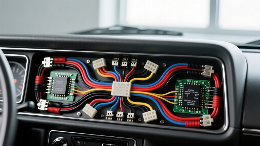
Anatomy of the GM C10 Instrument Panel Wiring Harness
The instrument panel wiring harness in 1973-1987 GM C10 square-body trucks represents a critical junction between the vehicle's primary bulkhead connector and the analog gauge cluster. Unlike modern vehicles that rely on multiplexed CAN-bus networks, these legacy harnesses utilize discrete, point-to-point analog circuits. Over decades of thermal cycling and vibration, the original PVC insulation becomes brittle, and the copper strands suffer from galvanic oxidation. Understanding the precise architecture of this harness is mandatory for any high-quality restoration, custom fabrication, or modern LS-swap integration.
At the core of the system is the printed circuit board (PCB) flex-circuit that mates with the harness connector. The harness itself routes through the firewall via a multi-pin bulkhead connector, branching off to feed the ignition switch, lighting circuits, and analog sending units. When replacing or repairing an instrument panel wiring harness, technicians must adhere to strict American Wire Gauge (AWG) specifications to prevent voltage drop, which directly translates to inaccurate gauge readings and dim indicator lamps.
Main Bulkhead Connector Pinout & Circuit Mapping
Below is the reference pinout for the primary 12-pin cluster connector found in most mid-70s to mid-80s GM truck platforms. Note that wire colors may vary slightly depending on the exact model year and whether the vehicle left the factory with a gauge package or an idiot-light package.
| Pin | Wire Color | AWG | Circuit Function |
|---|---|---|---|
| A | Pink | 14 | Ignition Switched 12V (Cluster Power) |
| B | Brown | 18 | Tail/Marker Lamp Feed (Illumination) |
| C | Dark Green | 18 | Right Turn Signal Indicator |
| D | Light Blue | 18 | High Beam Indicator |
| E | Dark Blue | 20 | Oil Pressure Sender Signal |
| F | Dark Green | 20 | Coolant Temperature Sender Signal |
| G | Yellow | 20 | Fuel Level Sender Signal |
| H | Black | 16 | Main Cluster Ground (G101) |
Common Failure Modes in Aging Instrument Cluster Harnesses
When diagnosing electrical gremlins behind the dash, it is crucial to recognize the specific failure modes inherent to aging instrument panel wiring harnesses. Simply swapping the gauge cluster rarely solves the issue if the underlying harness is compromised.
- Fretting Corrosion at Terminal Interfaces: Micro-movements caused by engine vibration wear away the tin plating on the male and female terminals. This exposes the underlying copper to oxygen, creating copper oxide—a semiconductor that introduces severe resistance into low-voltage analog sender circuits.
- Insulation Breakdown and Shorting: The original PVC insulation hardens over time. When the harness is bent during cluster removal, the insulation cracks, allowing adjacent 18 AWG illumination circuits to short against 20 AWG sender wires. This typically results in the fuel gauge pegging to 'Full' whenever the headlights are turned on.
- Ground Loop Interference: The main cluster ground (Pin H) relies on a ring terminal bolted to the dashboard frame. If this grounding point shares a path with high-current accessories like aftermarket stereo amplifiers or electric cooling fans, voltage differentials will cause the analog needles to flutter erratically.
Troubleshooting Decision Tree: Erratic Analog Gauges
Follow this diagnostic sequence when encountering erratic behavior in analog gauges connected to the instrument panel wiring harness:
- Verify Sender Resistance: Disconnect the harness at the engine block sender. Measure resistance to ground. GM standard senders typically read 0-90 ohms (fuel) or 10-135 ohms (temp). If out of spec, replace the sender.
- Check for Voltage Drop on the Signal Wire: Set your digital multimeter to DC Volts. Connect the positive probe to the harness side of the sender connector and the negative probe to the battery negative terminal. With the key ON, you should read less than 0.1V on an open circuit. A higher reading indicates a short to power in the harness.
- Isolate the Ground: Run a temporary 16 AWG jumper wire directly from the cluster housing to the negative battery terminal. If the gauges immediately stabilize, the factory G101 ground point is corroded or overloaded.
Voltage Drop Testing Methodology for Instrumentation
Analog gauges operate on the principle of thermal-electromagnetic balancing. The instrument panel voltage regulator (IVR) pulses 12V down to an average of 5.5V to 7.5V. If the wiring harness suffers from excessive resistance, the voltage reaching the gauge coil drops, causing the gauge to read artificially low. To test the harness integrity, perform a dynamic voltage drop test.
Place your multimeter probes across the entire length of the suspect circuit—from the ECM or fuse box output pin to the cluster PCB trace. With the circuit loaded (ignition ON), a healthy 14 AWG to 20 AWG wire should exhibit a voltage drop of no more than 0.05V to 0.1V. Any reading exceeding 0.2V mandates a harness repair or complete replacement. According to the SAE J1128 standard for low-tension primary cables, maintaining the correct cross-sectional area and minimizing terminal crimp resistance is vital for accurate instrumentation.
Integrating Modern LS-Swap ECMs with Legacy Harnesses
One of the most complex challenges in modern hot-rodding is adapting a Gen III/IV LS engine's digital outputs to a vintage instrument panel wiring harness. The LS ECM monitors coolant temperature and oil pressure via 5V reference thermistors and CAN-bus data, which are entirely incompatible with the legacy 1-wire analog variable-resistance senders expected by the C10 gauge cluster.
To bridge this gap without replacing the entire dash, fabricators use CAN-bus to analog signal converters. Devices like the Dakota Digital SGI-5C or similar ECM translators intercept the OBD-II CAN-bus data stream and generate a pulse-width modulated (PWM) signal. This PWM signal is then fed into a solid-state variable resistor module that physically mimics the 0-90 ohm and 10-135 ohm resistance curves required by the factory instrument panel wiring harness. When wiring the translator module into the harness, always use shielded twisted-pair (STP) cable for the CAN-High and CAN-Low lines to prevent electromagnetic interference (EMI) from the ignition coils from corrupting the data stream.
Splicing, Termination, and SAE J1128 Compliance
When repairing a damaged section of the instrument panel wiring harness, never use twist-on connectors or standard electrical tape. The environment behind a dashboard experiences extreme thermal fluctuations, which will cause adhesive-backed tape to melt and migrate, leaving bare copper exposed.
For professional-grade repairs that meet IPC-A-620 harness acceptability standards, utilize the following methodology:
- Wire Selection: Replace damaged segments with SAE J1128 compliant cross-linked polyethylene (XLPE) wire. XLPE offers superior abrasion resistance and can withstand temperatures up to 125°C, far exceeding the 80°C limit of standard PVC.
- Termination: Use open-barrel (F-style) crimp terminals rather than closed-barrel ring terminals. Open-barrel crimps provide a superior gas-tight seal when compressed with a dedicated ratcheting crimp tool, preventing oxygen ingress and subsequent galvanic corrosion.
- Sealing: Encapsulate all splices in dual-wall, adhesive-lined heat shrink tubing. The inner meltable adhesive layer flows into the wire strands, creating a waterproof environmental seal that prevents capillary action from drawing moisture under the insulation.
For those undertaking a complete ground-up restoration or a complex custom chassis build, sourcing a high-quality aftermarket replacement is often more reliable than attempting to salvage 40-year-old copper. Companies like Painless Performance offer fully terminated, color-coded instrument panel wiring harness kits that retain the OEM connector footprints while upgrading the wire insulation to modern XLPE standards and integrating dedicated relay circuits for high-draw accessories. By respecting the original pinouts and applying modern termination science, you ensure that your analog gauges remain accurate, responsive, and reliable for the next several decades of operation.