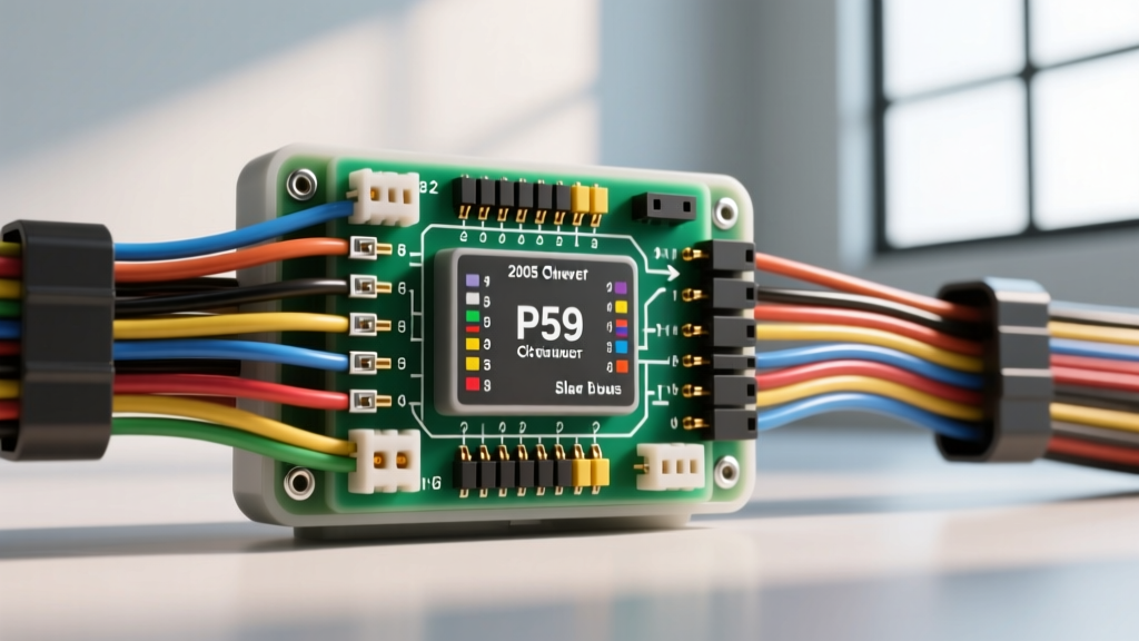
GMT800 Architecture: The 2005 Chevy Silverado Wiring Harness
The 2005 model year represents a critical evolutionary point in the GM GMT800 platform electrical architecture. Transitioning fully into the Gen III and early Gen IV powertrain era, the 2005 Chevy Silverado (equipped with the 4.8L LR4, 5.3L LMG/LY5, or 6.0L LQ4/LQ9) relies on a highly complex, multiplexed engine wiring harness. Unlike older PWM-driven systems, the 2005 harness manages Drive-By-Wire (DBW) electronic throttle control, sequential multi-port fuel injection, and high-speed serial data communication. For automotive electrical technicians and advanced DIYers, diagnosing faults within the 2005 Chevy Silverado wiring harness requires moving beyond simple continuity testing and understanding the specific topology of the P59 Powertrain Control Module (PCM), the Class 2 Serial Data bus, and the notorious under-manifold sensor circuits.
P59 PCM Connector Architecture and Pinout Matrix
The brain of the 2005 Silverado engine bay is the P59 PCM, which utilizes two primary 32-way Delphi connectors: C1 (Blue) and C2 (Red). These connectors utilize a mix of Delphi GT 150 and GT 280 terminals, sealed with silicone mat seals to prevent moisture ingress. When diagnosing a no-start condition, erratic idle, or communication failure, verifying the integrity of the power, ground, and ignition feeds at these specific pins is mandatory before condemning the PCM or the engine harness.
| Connector | Pin | Wire Color | Circuit Description | AWG |
|---|---|---|---|---|
| C1 (Blue) | 1 | Pink | Battery Positive (ECM Memory/Keep-Alive) | 18 |
| C1 (Blue) | 20 | Black/White | PCM Logic Ground | 18 |
| C1 (Blue) | 21 | Purple | Class 2 Serial Data Bus | 22 |
| C1 (Blue) | 31 | Dark Green | EVAP Purge Solenoid Control | 20 |
| C2 (Red) | 1 | Pink | Ignition 1 (Run/Start Feed) | 18 |
| C2 (Red) | 2 | Black/White | PCM Power Ground (High Current) | 18 |
| C2 (Red) | 14 | Dark Blue | Knock Sensor 1 Signal | 22 |
| C2 (Red) | 25 | Light Blue | Knock Sensor 2 Signal | 22 |
| C2 (Red) | 32 | Tan/Black | Fuel Pump Relay Control | 18 |
The Valley Cover Knock Sensor Harness Failure Matrix
One of the most pervasive and frustrating failure modes specific to the 2005 Chevy Silverado wiring harness involves the Knock Sensor (KS) sub-harness. On the 5.3L and 4.8L Vortec engines, the two knock sensors are mounted horizontally in the engine block valley, directly beneath the intake manifold. The wiring harness pigtails route through a small grommet at the rear of the valley cover.
Due to the extreme thermal cycling and the tendency for the valley cover gasket to weep oil or ingest condensation, the KS connectors are highly susceptible to galvanic corrosion and capillary wicking. When moisture breaches the connector seal, it travels up the 22 AWG Dark Blue (KS1) and Light Blue (KS2) wires directly into the P59 PCM C2 connector. This results in DTCs P0327 (Knock Sensor 1 Low Frequency) or P0332 (Knock Sensor 2 Low Frequency). Diagnostic Protocol: Do not simply replace the sensors. You must perform a megohmmeter insulation test on the KS harness pigtail. If resistance drops below 10 Megaohms to ground, the entire valley sub-harness must be replaced, and the PCM cavity must be inspected for green copper oxide corrosion.
Grounding Topology: G111, G112, and G103
GM's GMT800 grounding strategy relies heavily on localized engine block and cylinder head grounds. The 2005 Silverado engine harness utilizes three primary ground nodes that are notorious for causing cascading electrical failures when compromised:
- G111 (Left Cylinder Head): Secured via a 10mm bolt near the rear of the driver-side head. This ground handles the return path for the driver-side ignition coils and fuel injectors.
- G112 (Right Cylinder Head): Located on the passenger-side head, servicing the passenger-side injectors and coils.
- G103 (Engine Block/Intake): A critical braided ground strap connecting the engine block to the chassis/firewall, stabilizing the alternator output and starter return paths.
Failure Mode: The factory ring terminals on G111 and G112 often suffer from micro-fractures in the crimp barrel due to engine vibration. Furthermore, if the factory star washer is omitted during a previous repair, the ground connection will oxidize, leading to high-resistance returns. This causes the PCM to overcompensate by extending injector pulse width, resulting in a rich condition and erratic DBW throttle response. Always clean the mating surface to bare aluminum, apply a thin layer of dielectric grease to prevent oxidation, and torque the 10mm bolt to 106 lb-in (12 Nm) per Helm Inc. GM Factory Service Documentation.
Class 2 Serial Data Bus (SAE J1850 VPW) Diagnostics
The 2005 Silverado utilizes the Class 2 Serial Data bus, governed by the SAE J1850 VPW (Variable Pulse Width) protocol, operating at 10.4 kbps. This single-wire multiplexed network (Pin 21 on the C1 Blue PCM connector, typically a Purple 22 AWG wire) allows the PCM, Body Control Module (BCM), Instrument Panel Cluster (IPC), and Electronic Brake Control Module (EBCM) to share data without dedicating individual copper circuits for every parameter.
When diagnosing a Class 2 bus short or open circuit, technicians must locate the primary data splice pack, designated as SP205, located under the driver-side dash near the BCM. A common failure point is the corrosion of the SP205 splice pack terminals due to water intrusion from a clogged HVAC drain or windshield cowl. To diagnose, isolate the modules by pulling fuses one by one while monitoring the Class 2 data line with an oscilloscope. A healthy VPW signal will show a 0-7V square wave with variable pulse widths. A flatline at 0V indicates a short to ground, while a flatline at 7V indicates a short to voltage or an open termination resistor.
Accelerator Pedal Position (APP) Sensor Harness Routing
Because the 2005 Silverado utilizes a fully electronic Drive-By-Wire throttle system, the Accelerator Pedal Position (APP) sensor harness is a critical safety circuit. The APP sensor outputs three redundant signals (APP1, APP2, APP3) to the PCM to ensure throttle accuracy and fail-safe operation. The harness routes from the pedal assembly, through the firewall bulkhead connector, and into the engine bay.
The bulkhead connector is a known ingress point for moisture. If the silicone mat seal degrades, water enters the cavity and shorts the 5V reference circuits (typically Brown and Gray wires) to the signal returns. This triggers a reduced engine power (Limp Mode) state and DTC P2138 (APP Sensor 1-2 Correlation). When repairing this section of the harness, it is imperative to use Delphi Automotive Connection Systems approved GT 150 terminals and ensure the locking tang is fully seated to prevent terminal back-out under pedal vibration.
Physical Routing, Chafing Vectors, and Harness Repair
The physical routing of the 2005 Chevy Silverado engine harness exposes it to severe chafing vectors, most notably at the rear of the passenger-side cylinder head where the harness drops down to the rear Oxygen Sensors, and near the alternator bracket on the front driver side. The factory convoluted split-loom tubing often degrades due to UV exposure and underhood temperatures exceeding 125°C.
When performing harness repairs, avoid the use of twist-and-solder methods or standard electrical tape, which will melt and unravel in the engine bay. Instead, utilize an open-barrel crimping tool calibrated for Delphi GT 280 terminals, followed by adhesive-lined dual-wall heat shrink tubing (rated for 125°C). For severe harness degradation, particularly in the DBW throttle body pigtails or the rear O2 sensor drops, replacing the affected sub-harness with an OEM-spec molded pigtail kit is the only reliable method to restore factory impedance and moisture sealing standards.