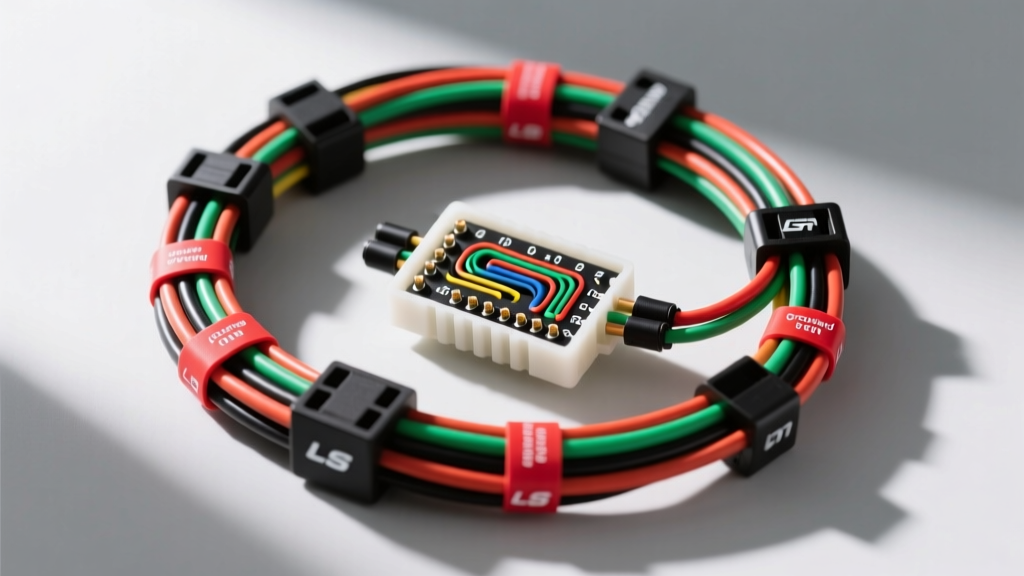
Understanding EFI Harness Architecture
Transitioning from a carburetor to electronic fuel injection (EFI) requires more than just bolting on a throttle body and injectors; it demands a robust nervous system to manage the complex data exchange between sensors, actuators, and the Powertrain Control Module (PCM). A dedicated fuel injection wiring harness is the critical bridge that ensures precise fuel delivery, ignition timing, and emissions compliance. In this comprehensive diagram walkthrough, we will dissect the anatomy of a GM LS-series (LS1/LS6) EFI harness—the gold standard for engine swaps—detailing exact wire colors, American Wire Gauge (AWG) specifications, Delphi connector pinouts, and real-world routing strategies.
Decoding the PCM Connector Pinouts
The GM LS PCM (commonly P/N 12200411 or 12212156) utilizes three primary harness connectors, each color-coded and designated for specific electrical domains. Understanding these domains is crucial when fabricating a custom harness or troubleshooting an OEM replacement.
C1 Connector (Black) - High Current Drivers
The C1 (Black) 80-pin connector is dedicated to high-current actuator controls, specifically the fuel injectors and ignition coils. The PCM uses internal low-side drivers to ground these circuits, triggering the injectors and coils. Because these circuits handle rapid switching and inductive kickback, the harness must utilize 18 AWG primary wire to handle the current without excessive voltage drop. The injectors are typically wired with a constant 12V switched feed (Pink wire) and a PCM-controlled ground path (Dark Green, Dark Blue, or Yellow/Black striped wires depending on the specific cylinder). The PCM integrates internal flyback diodes to suppress the voltage spikes generated when the coil primary windings are de-energized.
C2 Connector (Red) - Sensor Inputs & 5V Reference
The C2 (Red) 80-pin connector handles low-voltage analog sensor inputs, digital communication lines, and the critical 5-volt reference circuits. Sensors like the Mass Air Flow (MAF), Throttle Position Sensor (TPS), Intake Air Temperature (IAT), and Engine Coolant Temperature (ECT) rely on a stable 5V feed (typically a Gray wire) and a clean signal return (Light Blue or Black wire). Because these signals operate in the millivolt range, the fuel injection wiring harness must use 20 AWG wire for these circuits. Furthermore, the MAF and cam/crank sensor signals must be routed using twisted-pair configurations to cancel out electromagnetic interference (EMI) generated by the alternator and ignition coils.
C3 Connector (Blue) - Power, Ground, and Relays
The C3 (Blue) 32-pin connector is the lifeline of the PCM, providing main battery feeds, switched ignition power, and the primary PCM grounds. Pin 20 (Orange) supplies constant 12V battery memory to the PCM to retain fuel trims and diagnostic codes. Pin 11 (Pink) provides the switched 12V ignition wake-up signal. Crucially, Pins 31 and 32 (Black/White) serve as the primary PCM power grounds. If these ground circuits suffer from voltage drop, the 5V reference on the C2 connector will fluctuate, causing erratic fueling and phantom sensor codes.
Wire Gauge (AWG) and Terminal Specifications
Selecting the correct wire gauge and terminal type is non-negotiable for a reliable EFI system. Using undersized wire leads to voltage drop, while oversized wire can cause terminal splay and poor connector retention. Below is the specification chart for a standard LS-based fuel injection wiring harness.
| Circuit Type | Wire Gauge (AWG) | Terminal Series | Max Current | Typical GM Wire Color |
|---|---|---|---|---|
| Main PCM Power / Ground | 12 AWG | Metri-Pack 280 | 25A | Orange / Black-White |
| Fuel Pump Relay Feed | 10 AWG | Weather-Pack / Relay | 20A | Gray (to pump) |
| Injector / Coil Drivers | 18 AWG | Metri-Pack 280 / USCAR | 6A per circuit | Dark Green / Pink |
| 5V Reference / Sensor Signal | 20 AWG | Metri-Pack 150 | 0.5A | Gray / Light Blue |
| Switched Ignition Feed | 14 AWG | Metri-Pack 280 | 15A | Pink |
Bulkhead Routing and Grommet Sealing
When routing a fuel injection wiring harness from the engine bay into the passenger compartment, the firewall bulkhead pass-through is a major failure point. Engine bay temperatures, moisture, and vibration can rapidly degrade poorly sealed harnesses. Always use a molded rubber grommet with a minimum 3mm wall thickness. Before pulling the harness through, apply a dielectric silicone grease to the rubber grommet to prevent tearing. Once routed, fill the cavity of the grommet with RTV silicone or a dedicated harness sealing compound (like 3M Strip-Calk) to prevent water ingress and block toxic exhaust gases from entering the cabin.
Grounding Strategy: Star vs. Daisy Chain
The most common cause of erratic EFI behavior is a poor grounding strategy. Never 'daisy chain' grounds (e.g., grounding the PCM to the block, the block to the frame, and the frame to the battery). This creates ground loops and introduces alternator whine into the sensor circuits. Instead, utilize a star grounding approach. Run dedicated 12 AWG or 10 AWG ground wires from the PCM, cylinder heads, engine block, and fuel pump directly to a single, clean, bare-metal distribution point on the chassis or directly to the negative battery terminal. Always use serrated flange nuts or star washers to bite through the paint and ensure a zero-resistance connection to bare metal.
Real-World Troubleshooting: Common Harness Failures
Even the best-fabricated fuel injection wiring harness can develop faults over time. Here is a diagnostic decision tree for common EFI electrical issues:
- Symptom: Random Cylinder Misfires (P0300)
Cause: Loss of terminal tension in the coil pack connectors or chafed injector wires shorting to the intake manifold.
Fix: Perform a 'pin drag test' using a male Metri-Pack 280 terminal. If it slides into the female coil connector without resistance, the terminal is fatigued and must be replaced. Inspect the harness loom near the rear of the intake manifold for heat damage. - Symptom: Erratic Idle and Surging
Cause: Voltage drop on the PCM ground circuits or a compromised 5V reference line.
Fix: With the engine running and all accessories on, use a digital multimeter to measure the voltage between the PCM ground pin (C3 Pin 31) and the negative battery post. A reading above 0.05V indicates a high-resistance ground. Clean the ground ring terminal and mating surface with a wire wheel. - Symptom: Fuel Pump Runs Continuously or Not At All
Cause: Stuck fuel pump relay or chafed Purple wire (PCM relay control) shorting to ground.
Fix: Disconnect the C3 connector. If the fuel pump stops running, the PCM driver is internally shorted. If it continues to run, the Purple wire between the PCM and the relay is shorted to ground in the harness loom.
Authoritative References
For further technical validation on wire insulation standards and connector specifications, consult the following industry resources:
- SAE J1128: Low Tension Primary Cable Standard - Defines the thermal and electrical requirements for automotive primary wiring used in EFI harnesses.
- Delphi Automotive Connector Systems - Technical datasheets for Metri-Pack 150/280 terminal retention forces and current derating curves.
- Haynes Manuals: Wiring Harness Basics and Repair - Best practices for solder-sealing, crimping, and heat-shrink application in high-vibration engine environments.