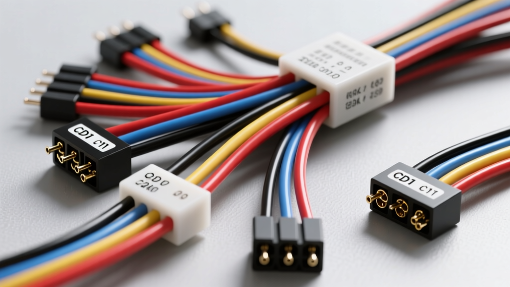
Decoding the Chinese Quad Wiring Harness
When working on 50cc to 250cc ATVs manufactured by brands like TaoTao, Kazuma, Roketa, Apollo, or Coolster, you will quickly realize that factory documentation is either missing or notoriously inaccurate. The generic Chinese quad wiring harness relies on a modular, mass-produced loom designed to fit a dozen different chassis configurations. While this keeps manufacturing costs low, it leaves owners and mechanics guessing when a stator fails, a CDI burns out, or the lighting circuit shorts.
This complete wiring diagram walkthrough decodes the standard electrical architecture found in almost all Chinese-manufactured utility and sport quads. We will break down the magneto stator outputs, the ubiquitous 6-pin Capacitor Discharge Ignition (CDI) module, the rectifier/regulator logic, and the ignition switch kill circuits. Whether you are troubleshooting a no-spark condition or fabricating a custom harness adapter, understanding these specific wire colors, pin configurations, and AWG requirements is critical for a reliable repair.
Core System 1: The Magneto Stator Output Decoder
The heart of the Chinese quad electrical system is the magneto stator located behind the left-side engine cover. Unlike modern fuel-injected machines that use a single high-output three-phase stator, these quads typically use a dual-coil or multi-pole single-phase stator. One coil is dedicated strictly to high-voltage ignition power, while the others handle lighting and battery charging.
Because factory wire colors can occasionally vary between production runs, always verify your stator output with a multimeter. However, the following color code represents the industry standard for 110cc, 125cc, and 150cc GY6 and horizontal engines.
| Wire Color | Function | Expected Output (Cranking) | Destination |
|---|---|---|---|
| Black / Red | Source / Ignition Power Coil | 100V - 400V AC | CDI Pin 1 |
| Blue / White | Trigger / Pulse Pickup Coil | 0.5V - 2.0V AC Pulse | CDI Pin 2 |
| Yellow / Yellow | AC Lighting Coil | 12V - 18V AC (RPM dependent) | Ignition Switch / Lights |
| White | DC Charging Coil | 14V - 28V AC (Pre-rectifier) | Rectifier / Regulator |
| Green | Stator Ground | Continuity to Engine Block | Chassis Ground |
Core System 2: The 6-Pin CDI Pinout Walkthrough
The most common point of failure and confusion in a Chinese quad wiring harness is the CDI unit. Most 50cc to 125cc quads use an AC-CDI, meaning it draws its primary firing power directly from the stator's Black/Red wire, not the battery. This allows the quad to run even with a completely dead battery. The CDI connector is a standard 6-pin JST-style block.
Below is the definitive pinout for the standard 6-pin AC-CDI. Note that inserting the plug backward or mis-wiring an adapter harness will instantly destroy the internal Silicon Controlled Rectifier (SCR) and the ignition coil.
| Pin Number | Wire Color (Harness Side) | Function & Electrical Logic |
|---|---|---|
| Pin 1 | Black / Red | Source Power: Receives 100V+ AC from the stator source coil. Rectified internally to charge the main capacitor. |
| Pin 2 | Blue / White | Trigger Signal: Receives the low-voltage pulse from the pickup coil, telling the SCR to dump the capacitor's charge. |
| Pin 3 | Black / Yellow | Ignition Coil Feed: Outputs 200V-400V DC to the primary winding of the ignition coil to create the spark. |
| Pin 4 | Green / White | Kill Switch Input: When grounded, it shorts the internal circuit, preventing the capacitor from charging. |
| Pin 5 | Black / White | CDI Ground: Must have clean continuity to the engine block. A poor ground here causes weak or intermittent spark. |
| Pin 6 | White (or unused) | Lighting / DC Feed: On some DC-CDI variants, this receives 12V DC from the battery. On pure AC-CDIs, this pin is often empty. |
Core System 3: Rectifier/Regulator and Battery Charging
The charging system on these quads utilizes a simple single-phase shunt-style regulator/rectifier. It takes the raw, fluctuating AC voltage from the stator's White wire, converts it to DC, and clips the excess voltage to prevent the 12V battery from boiling over.
The standard connector is a 4-pin or 5-pin block. If you are adapting a harness, the wiring logic is as follows:
- Yellow (x2): AC Input from the stator lighting/charging coils. These are non-polarized and can be swapped without issue.
- Red: DC Output (13.8V - 14.4V regulated). This routes directly to the battery positive terminal and the main harness fuse block.
- Green: System Ground. This must be bolted directly to the frame or engine case to handle the heat dissipation and provide a stable reference voltage for the regulator.
Expert Tip: The factory 14 AWG red wire leading from the rectifier to the battery is often too thin for the high-amperage spikes generated when the quad is winching or using high-wattage aftermarket lights. Upgrading this specific run to SAE J1128 compliant 10 AWG primary wire will prevent voltage drop and melted connectors.
Core System 4: Ignition Switch and Kill Circuit Logic
Understanding the kill circuit is vital for troubleshooting a Chinese quad wiring harness. Unlike modern vehicles that use a digital ECU to cut fuel and spark, these quads use a hardwired physical ground to kill the ignition.
The standard 4-pin ignition switch operates as follows:
- Red Wire: Constant 12V DC from the battery positive.
- Black Wire: Switched 12V DC output to the harness (powers the horn, turn signals, and DC accessories).
- White Wire: Switched AC from the stator Yellow wire (powers the headlights and taillights). This is why your headlights flicker at idle and only turn on when the key is in the "ON" or "LIGHTS" position.
- Green / Black Wire: The Kill Wire. When the key is turned to "OFF", this wire is internally bridged to the Green ground wire inside the switch, grounding out CDI Pin 4 and stopping the engine.
Advanced Troubleshooting: No-Spark Diagnostic Tree
When a Chinese quad refuses to start and you suspect a harness or ignition fault, follow this strict diagnostic sequence to isolate the failure point. According to testing procedures outlined by Rick's Motorsport Electrics, testing under cranking RPM is mandatory, as stator output is RPM-dependent.
Step 1: Verify the Kill Circuit
Disconnect the 6-pin CDI harness. Set your multimeter to continuity mode. Probe the harness-side Green/White wire (Pin 4) and a known good engine ground. With the key "ON" and the tether switch "ENGAGED", there should be NO continuity (OL). If you read continuity, your ignition switch, tether lanyard, or handlebar kill button is shorted to ground, killing the spark before it begins.
Step 2: Test Stator Source Power
Set the multimeter to AC Volts (200V+ scale). Probe the harness-side Black/Red wire (Pin 1) while cranking the engine. You must see a minimum of 80V AC. If you read 0V or less than 20V, the internal stator source coil is burnt out, or the Black/Red wire is severed inside the harness sheath near the stator cover.
Step 3: Test Trigger Pulse
Set the multimeter to AC Volts (2V scale). Probe the Blue/White wire (Pin 2) while cranking. You should see a rapid pulse between 0.5V and 2.0V AC. If absent, the pickup coil has failed, or the air gap between the pickup and the flywheel magneto tab is too wide (spec is typically 0.020" - 0.030").
Step 4: Isolate the Ignition Coil
If the CDI is receiving power and trigger signals, but there is no spark at the plug, test the ignition coil primary resistance. Disconnect the Black/Yellow wire. Measure resistance between the coil's primary terminal and the coil's ground tab. It should read between 0.1 and 0.5 ohms. Next, measure secondary resistance from the spark plug cap to the ground tab (typically 3,000 to 5,000 ohms). If the coil tests good, the CDI unit has failed internally.
Harness Upgrades: Connectors and Environmental Sealing
The weakest link in any Chinese quad wiring harness is the use of cheap, unsealed nylon connectors with thin brass pins. These connectors suffer from terminal fretting, moisture ingress, and vibration-induced disconnects. When repairing or extending a harness, abandon the factory connectors in high-exposure areas.
Upgrade the stator-to-harness connection and the CDI plug using Deutsch DT series or Sumitomo HM sealed connectors. These utilize silicone seals and copper-alloy crimp terminals that resist corrosion. Furthermore, always pack the cavity of the ignition switch and the CDI connector with a high-dielectric silicone grease (such as 3M Silicone Paste) to prevent the green corrosion that plagues ATV electrical systems after a season of mud and water exposure.
For comprehensive community-driven wiring diagrams and model-specific harness variations, the ThumperTalk ATV General Tech forums remain an invaluable resource for cross-referencing obscure factory harness revisions across different import years.
Summary
Mastering the Chinese quad wiring harness requires looking past the lack of factory manuals and understanding the fundamental logic of magneto-driven AC/DC systems. By memorizing the stator color codes, respecting the CDI pinout logic, and upgrading the sub-standard factory wire gauges and connectors, you can transform an unreliable import ATV into a dependable machine capable of handling harsh off-road environments.