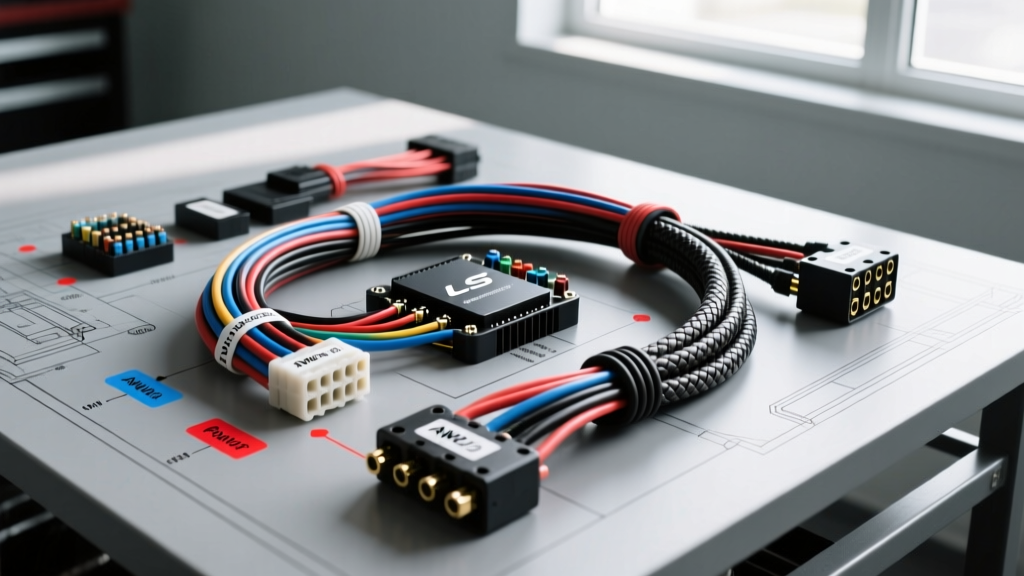
Phase 1: Schematic Deconstruction and Load Calculation
Designing a custom wiring harness for an engine swap—such as integrating a 5.3L LS V8 into a classic 1969 Camaro chassis—requires moving beyond simple point-to-point connections. True electrical wiring harness design begins with a rigorous load calculation and schematic deconstruction. Before cutting a single length of wire, you must categorize every circuit by its amperage draw and duty cycle.
Automotive circuits generally fall into two categories: continuous loads (e.g., PCM memory, fuel injection logic) and intermittent/high-inrush loads (e.g., starter solenoids, cooling fans, fuel pumps). A standard LS1 electric fuel pump draws roughly 8 to 12 amps continuously, but its inrush current upon startup can spike to 25 amps for a fraction of a second. If your harness design relies on a 10A fuse and 14 AWG wire without accounting for inrush spikes and voltage drop over long runs to the rear fuel cell, you risk nuisance blown fuses and fuel starvation under heavy load.
Phase 2: Wire Gauge Selection and Insulation Standards
The backbone of any reliable harness is the wire itself. Never use standard PVC-insulated wire (like THHN or generic hardware store wire) in an automotive engine bay. PVC becomes brittle, melts against exhaust components, and degrades from oil exposure. Professional harness design mandates the use of cross-linked polyethylene (XLPE) insulated wire, specifically TXL, GXL, or SXL, as defined by the SAE J1128 Low Tension Primary Cable Standard.
- TXL (Thin Wall): Best for tight spaces and modern high-density connectors. Rated up to 125°C.
- GXL (General Wall): The industry standard for aftermarket harnesses. Excellent balance of flexibility and abrasion resistance. Rated up to 125°C.
- SXL (Standard Wall): Thickest insulation. Used for high-heat areas near exhaust manifolds or heavy-gauge battery cables. Rated up to 125°C.
AWG Sizing and Amperity Chart for LS Harnesses
| AWG Size | Max Amperage (Engine Bay) | Primary Application in LS Swap | Recommended Fuse |
|---|---|---|---|
| 18 AWG | 6A - 8A | PCM sensor signals, injectors, 5V references | 5A - 10A |
| 16 AWG | 10A - 12A | Ignition coils (COP), interior dash feeds | 10A - 15A |
| 14 AWG | 15A - 18A | Fuel pump relays, cooling fan low-speed | 15A - 20A |
| 12 AWG | 20A - 25A | Main PCM power feeds, cooling fan high-speed | 25A - 30A |
| 10 AWG | 30A - 40A | Alternator B+ output, main power distribution | 40A - 50A |
| 4 AWG | 100A - 120A | Battery to starter, main chassis ground | Mega Fuse 125A |
Always adhere to the IPC/WHMA-A-620 Standard for crimping profiles. A proper open-barrel crimp on a Metri-Pack terminal must exhibit a visible 'wire brush' (strands extending slightly past the terminal) and a distinct 'bellmouth' at the insulation crimp to prevent the insulation from cutting into the copper strands during vibration.
Phase 3: Connector Selection and PCM Pinout Mapping
Connector selection dictates the long-term reliability of your electrical wiring harness design. Spade terminals and butt connectors have no place in a modern EFI engine harness. You must use sealed, locking connectors.
- Delphi Metri-Pack 2.8: The standard for GM PCM connections, sensors, and high-current injector feeds. Features a robust secondary lock (TPA) to prevent terminal back-out.
- Weatherpack: Ideal for older style sensors, bulkhead pass-throughs, and heavy-duty lighting circuits. Excellent moisture sealing but bulkier than Metri-Pack.
- Deutsch DT Series: The gold standard for high-vibration, high-moisture environments. Use these for fuel pump modules, transmission solenoids, and external cooling fan motors.
LS1 PCM Connector Pinout Reference (C1 Blue & C2 Red)
When designing the harness from the PCM outward, mapping the primary power, ground, and output pins is critical. Below is a foundational reference for a standard 1999-2002 LS1 PCM harness design.
| Connector | Pin Number | Wire Color (OEM Spec) | Circuit Function | Wire Gauge |
|---|---|---|---|---|
| C1 (Blue) | 1 | Pink | Ignition 12V+ (Fused) | 14 AWG |
| C1 (Blue) | 2 | Black/White | PCM Main Ground | 12 AWG |
| C1 (Blue) | 20 | Dark Green | Tachometer Output Signal | 18 AWG |
| C1 (Blue) | 59 | Dark Green | Class 2 Serial Data (OBD2) | 18 AWG |
| C2 (Red) | 1 | Dark Green/White | Fuel Pump Relay Control (Low Side) | 18 AWG |
| C2 (Red) | 30 | Dark Green | Cooling Fan 1 Relay Control | 18 AWG |
Expert Insight: Pin 1 on the C2 connector controls the fuel pump relay via a low-side driver. This means the PCM provides the ground path to trigger the relay. Do not send 12V+ to this pin, or you will instantly fry the PCM's internal driver transistor. Always use a standard Bosch-style ISO mini relay (Pins 30, 87, 85, 86) and wire Pin 85 to the PCM's low-side output.
Phase 4: Routing, Looming, and Environmental Protection
A flawless schematic will fail if the physical routing ignores the harsh realities of an engine bay. The Painless Performance LS Harness Manual emphasizes maintaining strict clearances from heat sources and moving components.
Environmental Protection Hierarchy
- Dual-Wall Adhesive Heat Shrink: Use this at every connector backshell and splice. The inner wall melts and seals out moisture, preventing capillary action from wicking water into the copper strands.
- Split Loom (Corrugated Tubing): Excellent for abrasion resistance against sheet metal and firewall pass-throughs. However, it traps heat and moisture if not sealed at the ends.
- Expandable Braided Sleeving (Techflex): Best for high-heat areas and aesthetic engine bay routing. It does not trap moisture and allows for easy visual inspection of the wires.
- Firesleeve (Silicone-Coated Fiberglass): Mandatory for any wire routing within 4 inches of exhaust headers or turbochargers. Rated to withstand 500°F continuous heat.
Failure Mode Alert: A common mistake in LS swap harness design is routing the O2 sensor harnesses over the top of the bellhousing or near the exhaust crossover. The radiant heat bakes the Teflon insulation, causing the sensor signal wires to short together, resulting in phantom lean codes (P0171/P0174) and severe engine detonation.
Phase 5: Grounding Strategy and Voltage Drop Testing
The most overlooked aspect of electrical wiring harness design is the return path (ground). Modern EFI systems rely on ultra-precise 5-volt reference signals. A poor ground will introduce resistance, skewing sensor data and causing erratic idle or transmission shift flares.
The Star Ground Method vs. Daisy Chaining
Never 'daisy chain' grounds (connecting Component A to Component B, then to the chassis). If Component A draws heavy current, the voltage drop across the shared wire will alter the ground reference for Component B. Instead, use a Star Ground architecture. Run individual ground wires from every major component (PCM, injectors, coils) to a single, massive central grounding bus bar or a dedicated, clean stud welded to the engine block or chassis.
Performing a Voltage Drop Test
Do not rely on a continuity beep from a multimeter; it cannot detect high resistance under load. Perform a dynamic voltage drop test:
- Set your digital multimeter to DC Millivolts (mV).
- Turn the circuit ON (e.g., command the cooling fan on via a scan tool).
- Place the RED probe on the battery's negative terminal.
- Place the BLACK probe on the component's ground terminal (past the connector).
- Acceptable Limit: Less than 100mV (0.1V) for high-current power grounds. Less than 50mV (0.05V) for sensitive PCM sensor grounds.
Troubleshooting Decision Tree: Common Harness Design Flaws
When your custom harness exhibits gremlins post-installation, use this diagnostic decision tree to isolate the design flaw:
- Symptom: PCM resets or loses memory when the starter engages.
- Cause: Voltage drop on the main PCM B+ feed or ignition switch circuit during the 200A+ starter draw.
- Fix: Upgrade the PCM constant 12V+ feed to 12 AWG, route it directly to the alternator B+ post or battery positive with a dedicated 15A fuse, bypassing the factory ignition switch bulkhead.
- Symptom: Fuel pump relay clicks rapidly or PCM throws a 'Fuel Pump Relay Control Circuit' DTC.
- Cause: Inductive kickback from the relay coil destroying the PCM's low-side driver.
- Fix: Solder a 1N4001 flyback diode across the relay coil pins (85 and 86), with the diode's stripe facing the 12V+ trigger side, to absorb the reverse voltage spike.
- Symptom: Alternator whine in the audio system or erratic TPS readings.
- Cause: Sensor ground wires routed parallel to high-current charging wires, inducing electromagnetic interference (EMI).
- Fix: Reroute low-voltage analog signal wires (TPS, MAF, O2) at a strict 90-degree angle to any high-current alternator or ignition coil feeds.
Mastering electrical wiring harness design is an exercise in physics, patience, and precision. By adhering to SAE standards, utilizing proper sealed connectors, and validating your work with voltage drop testing, you ensure your LS swap will start on the first key turn and run reliably for tens of thousands of miles.