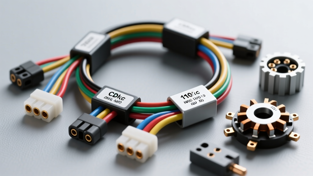
Introduction to 110cc Horizontal Engine Electrical Architecture
The 110cc horizontal single-cylinder engine platform—popularized by the Honda CRF110F and extensively cloned by manufacturers like Lifan, YX, and SSR—relies on a compact, magneto-driven electrical system. Understanding the 110cc wiring harness diagram is critical for diagnosing no-spark conditions, upgrading to DC lighting, or performing complete engine swaps into custom pit bike and mini ATV chassis. Unlike modern fuel-injected systems, these engines utilize a Capacitor Discharge Ignition (CDI) paired with a multi-pole stator to generate both high-voltage spark and low-voltage alternating current (AC) for lighting and battery charging.
This technical specification reference breaks down the exact wire color codes, pinout configurations, American Wire Gauge (AWG) requirements, and multimeter testing procedures required to troubleshoot, repair, or fabricate a custom 110cc wiring harness. Whether you are dealing with a standard AC stator (lighting runs directly off the stator) or a DC stator (all power routed through a rectifier to a battery), the foundational stator outputs remain consistent across the platform.
110cc Stator Wire Color Code and Function Reference
The stator is the heart of the 110cc electrical system, housing the source coil, trigger coil, and lighting coils. The internal enameled copper windings transition to stranded harness wires at the stator grommet. Below is the universal color code matrix for 110cc horizontal engines.
| Wire Color | Function | Destination | Typical Output / Resistance |
|---|---|---|---|
| Black/Red | Source Coil (Exciter) | CDI Unit (Pin 1) | 100 - 400 Ω / 100-400V AC |
| Blue/White | Trigger / Pickup Coil | CDI Unit (Pin 2) | 90 - 170 Ω / 0.5-2.0V AC |
| Yellow | Lighting Coil 1 (AC) | Headlight Switch / Regulator | 0.1 - 1.0 Ω / 12-35V AC |
| White | Lighting Coil 2 (AC/DC) | Rectifier/Regulator | 0.1 - 1.0 Ω / 12-35V AC |
| Green | Common Ground | Chassis / Engine Block | Continuity (< 0.5 Ω) |
Note: Some aftermarket 110cc stators may use a solid Pink wire for the AC headlight tap instead of Yellow. Always verify continuity to the stator core and lighting windings if color codes deviate from the OEM Honda/Lifan standard.
5-Pin CDI Connector Pinout Specifications
The vast majority of 110cc engines utilize a 5-pin CDI module. The CDI takes the low-voltage AC pulse from the source coil, stores it in a capacitor, and releases it to the ignition coil the exact millisecond it receives the trigger signal from the pickup coil. Miswiring the CDI connector is the leading cause of aftermarket harness failures and blown CDI units.
Standard 5-Pin CDI Mapping
- Pin 1 (Black/Red): Source Coil Input. Receives high-voltage AC from the stator exciter winding to charge the internal capacitor.
- Pin 2 (Blue/White): Trigger Signal Input. Receives the low-voltage pulse from the flywheel pickup magnet, dictating exact ignition timing.
- Pin 3 (Green): System Ground. Must have a clean, bare-metal connection to the engine block or main chassis ground bus.
- Pin 4 (Black/White): Kill Switch Circuit. This is a Normally Open (NO) ground-kill circuit. When the handlebar kill switch is engaged, this pin is shorted to ground, dumping the capacitor charge and stopping the spark.
- Pin 5 (Black/Yellow): Ignition Coil Output. Sends the high-voltage discharge to the primary side of the external ignition coil.
Rectifier/Regulator 4-Pin Wiring Mapping
If your 110cc application includes a 12V battery for DC lighting, electric start, or auxiliary accessories, the harness must route the stator's AC output through a 4-pin Rectifier/Regulator. This component converts the alternating current to direct current and shunts excess voltage to ground to prevent boiling the battery.
- Yellow Wire: AC Input from Stator Lighting Coil.
- White Wire: AC Input from Stator Lighting Coil (often shared with the AC headlight tap on half-wave systems).
- Green Wire: Ground. Crucial for the shunt-regulation function. Without a solid ground, the regulator cannot bleed off excess voltage, leading to battery overcharge and blown 12V bulbs.
- Red Wire: DC 12V Output. Routes to the main harness fuse block and battery positive terminal.
Wire Gauge (AWG) and SAE Material Standards
When fabricating or repairing a 110cc wiring harness, selecting the correct wire gauge is non-negotiable. The harsh, high-vibration environment of a small displacement engine demands flexible, multi-strand copper wire. According to the SAE J1128 Low Tension Primary Cable Standard, automotive wire must withstand extreme thermal cycling and chemical exposure.
AWG Specification Chart
| Circuit Type | Recommended AWG | Metric Equivalent | Insulation Type |
|---|---|---|---|
| Stator to CDI (Signal) | 18 AWG | 0.82 mm² | XLPE or PVC (105°C) |
| Lighting / Regulator (AC) | 16 AWG | 1.31 mm² | PVC (105°C) |
| Main DC Battery Feed | 12 AWG | 3.31 mm² | XLPE (125°C) |
| Ignition Coil Primary | 16 AWG | 1.31 mm² | PVC (105°C) |
For connectors, avoid generic spade terminals which vibrate loose. Use sealed 2.5mm pitch JST-style connectors or Sumitomo HM 090 series waterproof housings with copper-alloy crimp terminals. Apply dielectric grease to all stator and CDI connections to prevent galvanic corrosion caused by water ingress and dissimilar metal contact.
Step-by-Step Multimeter Testing for 110cc Stator Coils
Before replacing a CDI or ignition coil, you must verify the stator outputs using a digital multimeter (DMM). Reference the diagnostic procedures outlined by RMSTATOR Technical Resources for precise powersport testing methodologies.
Static Resistance Testing (Engine Off)
- Set your DMM to the Ohms (Ω) setting (200 or 2k range).
- Disconnect the main stator harness connector.
- Test the Source Coil: Place probes on the Black/Red wire and Green (Ground). Expected reading: 100 - 400 Ω. An 'OL' (Open Loop) reading indicates a broken internal winding.
- Test the Trigger Coil: Place probes on the Blue/White wire and Green (Ground). Expected reading: 90 - 170 Ω.
- Test the Lighting Coils: Place probes on Yellow and White wires to Green. Expected reading: 0.1 - 1.0 Ω. A reading of 0.0 Ω indicates a short to ground inside the stator casing.
Dynamic AC Voltage Testing (Engine Running)
- Set your DMM to AC Volts (200V range).
- Back-probe the stator connector while the engine is idling.
- Measure Black/Red to Green: Should read 100V - 150V AC at idle, climbing to 300V+ at 5000 RPM.
- Measure Yellow/White to Green: Should read 12V - 15V AC at idle, climbing to 35V+ at high RPM. If voltage does not increase with RPM, the flywheel magnets may be demagnetized or the lighting coil is failing under load.
Common Failure Modes and Troubleshooting Decision Tree
Electrical gremlins on 110cc pit bikes and ATVs usually stem from vibration-induced harness damage or improper grounding. Use this decision tree to isolate the fault.
Symptom: No Spark at the Plug
- Step 1: Disconnect the Black/White (Kill Switch) wire at the CDI. If spark returns, the handlebar kill switch or tether lanyard is shorted to ground. Fix: Replace kill switch or repair chafed harness near the steering stem.
- Step 2: Check Blue/White trigger coil resistance. If out of spec (90-170 Ω), the pickup coil is dead. Fix: Replace stator assembly.
- Step 3: Verify 12V DC is reaching the ignition coil primary wire (if using a DC-CDI variant, though most 110cc are AC-CDI). Check the Black/Yellow wire for continuity from CDI Pin 5 to the coil.
Symptom: Battery Overcharging / Boiling
- Step 1: Check the Green wire on the Rectifier/Regulator. If the ground connection is corroded or loose, the regulator cannot shunt excess AC voltage. Fix: Sand the frame grounding point to bare metal and apply conductive anti-seize.
- Step 2: Test DC voltage at the battery while revving to 5000 RPM. If voltage exceeds 14.8V DC, the internal shunt diode in the regulator has failed. Fix: Replace the 4-pin rectifier/regulator.
Symptom: Headlight Blows Out at High RPM
- Cause: The bike is wired with an AC stator output directly to the headlight bulb without a regulating switch or DC conversion. The AC voltage spikes to 35V+ at high RPM, destroying standard 12V halogen bulbs.
- Fix: Install an AC voltage regulator inline with the Yellow headlight wire, or convert the entire lighting system to DC by routing the stator through the rectifier and powering the headlight switch from the 12V battery bus.
By strictly adhering to these wiring diagrams, pinout specifications, and SAE material standards, you can build a 110cc electrical system that is resilient, reliable, and capable of handling the rigorous demands of off-road and track environments.