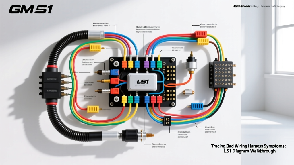
Decoding the GM LS1 Engine Harness: When Bad Wiring Harness Symptoms Mimic Component Failure
When diagnosing late-model V8 engines, particularly the legendary GM LS1 and LS6 platforms (1997-2004), technicians frequently encounter a frustrating scenario: replacing sensors, injectors, or even the Powertrain Control Module (PCM) fails to resolve the drivability issue. This is the hallmark of bad wiring harness symptoms. Because the LS1 engine harness routes critical 14 AWG and 18 AWG circuits through high-heat zones near the exhaust manifolds and tight pinch-points at the rear of the intake manifold, the wiring itself is often the true culprit.
In this complete wiring diagram walkthrough, we will trace the most common bad wiring harness symptoms on the GM F-Body and Corvette LS1 engine harness. By following the circuit paths from the PCM connectors (C1, C2, and C3) to the end components, you can accurately differentiate between a failed component and a degraded harness requiring an OEM replacement or custom aftermarket harness kit.
Anatomy of the LS1 Engine Harness Connectors
Before tracing symptoms, you must understand the physical interface. The LS1 engine harness terminates at the PCM via three primary connectors:
- C1 (Blue): 80-pin connector. Handles injector control, ignition coil control, and primary engine grounds.
- C2 (Red): 80-pin connector. Manages transmission controls, EVAP, and secondary sensor inputs.
- C3 (Clear/Black): 40-pin connector. Dedicated to the Mass Air Flow (MAF), Throttle Position Sensor (TPS), and critical 5V reference circuits.
According to SAE J1128 standards, the primary wire used in these harnesses is GXL (Cross-linked) insulation, rated for continuous operation up to 125°C. However, prolonged exposure to radiant exhaust heat exceeding 150°C causes the insulation to become brittle, leading to micro-fractures that create intermittent high-resistance faults.
Symptom-to-Circuit Walkthrough: Pinpointing the Failures
1. Random Misfires and P020X Injector Circuit Codes
The Symptom: The engine exhibits a random misfire at idle that worsens under load, accompanied by P0201-P0208 codes. You have swapped coils and injectors, but the code follows the cylinder.
Diagram Trace: The fuel injector circuit is a simple switched-ground design. A 14 AWG Pink wire supplies fused 12V ignition power to the injector harness splice pack. The PCM completes the circuit by grounding the 18 AWG control wire (e.g., Brown/White for Injector 1) via the C1 Blue connector.
The Failure Mode: The most common bad wiring harness symptom here occurs where the injector harness wraps behind the rear of the aluminum intake manifold. The harness rubs against the sharp casting edge or the EGR tube, wearing through the GXL insulation. This causes the PCM driver to short to ground or the 12V feed to short to the control wire, instantly frying the PCM injector driver.
| Cylinder | PCM Pin (C1 Blue) | Control Wire Color | Feed Wire Color |
|---|---|---|---|
| 1 | 73 | Brown/White | Pink (14 AWG) |
| 2 | 72 | Brown/Black | Pink (14 AWG) |
| 3 | 71 | Light Blue/White | Pink (14 AWG) |
| 4 | 70 | Light Blue/Black | Pink (14 AWG) |
| 5 | 69 | Yellow/White | Pink (14 AWG) |
| 6 | 68 | Yellow/Black | Pink (14 AWG) |
| 7 | 67 | Green/White | Pink (14 AWG) |
| 8 | 66 | Green/Black | Pink (14 AWG) |
2. Crank/No-Start and the 24X Crank Sensor (CKP)
The Symptom: Engine cranks but will not start. Scan tool shows 0 RPM while cranking. Replacing the CKP sensor yields no change.
Diagram Trace: The LS1 uses a 3-wire Hall-effect CKP sensor located above the starter motor. The harness routes a Yellow/Black (12V feed), Light Blue (Low Reference/Ground), and Purple (Signal) wire through a 3-pin Metri-Pack 150 connector. The Purple signal wire routes directly to Pin 21 on the C2 Red PCM connector.
The Failure Mode: Because this harness segment drops down behind the passenger side cylinder head, it is subjected to extreme radiant heat from the exhaust manifold. The 18 AWG Purple signal wire often suffers from internal copper strand fatigue due to thermal expansion and contraction cycles. A multimeter continuity test might show 0.5 ohms at rest, but under heat, the micro-fractures separate, dropping the signal voltage below the PCM's 2.5V threshold.
3. Erratic Idle, Stalling, and TPS/MAF Grounding Issues
The Symptom: Surging idle, stalling when coming to a stop, and erratic MAF readings (Hz fluctuating wildly). Codes P0102 or P0122 may be present.
Diagram Trace: Both the MAF and TPS rely on a shared 5V reference and a dedicated low-reference ground path back to the PCM. The Black ground wires exit the harness and terminate at ground studs G101 (Left rear cylinder head) and G102 (Right rear cylinder head).
The Failure Mode: Bad wiring harness symptoms in the ground circuit rarely involve broken wires; instead, they involve terminal corrosion and galvanic oxidation. The ring terminals at G101/G102 are prone to moisture ingress. Even a 0.5V voltage drop on the sensor ground circuit will skew the MAF sensor output, tricking the PCM into adding or subtracting fuel incorrectly. Always perform a voltage drop test across the ground circuit while the engine is running; any reading above 0.1V indicates a harness or terminal failure.
Diagnostic Decision Tree: Harness vs. Component
Use this structured diagnostic approach to confirm if bad wiring harness symptoms are truly the root cause before ordering replacement parts.
- Step 1: Visual Inspection. Peel back the convoluted tubing. Look for melted loom, exposed copper, or green/white copper oxide corrosion inside the Metri-Pack 280 connectors.
- Step 2: Pin Drag Test. Disconnect the PCM and the component. Use a test pin of the correct gauge to check terminal tension. If the test pin slides in without resistance, the female terminal is expanded and must be replaced.
- Step 3: Loaded Voltage Drop Test. Do not rely on simple continuity tests. A wire with a single intact copper strand will show continuity but will fail under load. Connect a headlight bulb or power probe to draw 2-3 amps across the circuit, then measure voltage drop. A drop exceeding 0.2V on a 12V feed or 0.1V on a ground confirms high harness resistance.
- Step 4: Wiggle Test with Heat. Use a heat gun (set to 200°F) on suspected harness segments while monitoring live data. If the sensor reading spikes when heat is applied, the internal wire is fractured.
Repair vs. Replacement: Choosing the Right Harness Kit
When bad wiring harness symptoms are isolated to a single chafed wire or a corroded connector pigtail, a targeted repair is viable. However, you must use OEM-style ratcheting crimp tools designed specifically for Metri-Pack 150 and 280 terminals. Never use generic pliers. Furthermore, avoid soldering splices in engine harnesses. Solder wicks into the copper strands via capillary action, creating a rigid, inflexible joint. In the high-vibration environment of an LS1 engine bay, this hard point will quickly fatigue and snap. Instead, use stepped heat-shrink butt connectors with marine-grade adhesive lining to seal out moisture and maintain flexibility.
If the harness exhibits widespread insulation brittleness, multiple melted segments near the exhaust, or severe green copper-oxide corrosion inside the main PCM cavities, a complete harness replacement is mandatory. For engine swaps or heavily degraded OEM harnesses, upgrading to an aftermarket wiring harness kit ensures modern TXL or XLPE wire is used, providing superior heat resistance and flexibility. When selecting a replacement harness kit, verify that the kit includes the correct PCM bulkhead grommets, pre-terminated weatherproof connectors, and the exact pinout mapping for your specific PCM operating system. For example, 1999-2000 LS1 PCMs utilize a completely different injector driver logic and pinout compared to the 2001-2004 LS1/LS6 PCMs; installing the wrong harness kit will result in immediate injector circuit codes and potential PCM damage.
For further reading on terminal retention and connector specifications, refer to the Delphi Automotive Connector Catalog and standard Motor Information Systems electrical diagnostic procedures.