Diagnostic Decision Tree: Symptom to Fault Isolation
Before initiating a transmission wiring harness repair, technicians must accurately isolate the fault to avoid unnecessary parts replacement. Modern automatic transmissions rely on pulse-width modulated (PWM) solenoids, speed sensors, and temperature sensors routed through a primary bulkhead connector. Use the following decision tree to map your OBD-II diagnostic trouble codes (DTCs) and physical symptoms to specific harness failure points.
- Symptom: Erratic Shifting / Limp Mode (P0700, P0753, P0758)
- Probable Cause: External harness chafing near the bellhousing or exhaust crossover, causing a short-to-ground on Shift Solenoid A or B control circuits.
- Verification: Perform a wiggle test with a digital volt-ohm meter (DVOM) while monitoring resistance at the PCM connector.
- Symptom: No Torque Converter Clutch (TCC) Lockup (P0740, P0742)
- Probable Cause: Internal harness connector pin fretting or ATF fluid intrusion causing a high-resistance open on the TCC PWM solenoid circuit.
- Verification: Drop the transmission pan and test solenoid resistance directly at the internal bulkhead connector.
- Symptom: Harsh 2-3 Shift / Flare (P0785)
- Probable Cause: Internal wiring harness insulation degradation due to prolonged exposure to high-temperature synthetic ATF, leading to cross-talk between the 3-2 shift solenoid and line pressure control solenoid.
- Verification: Inspect internal harness for brittle, flaking insulation (typically seen on high-mileage GM 4L60E/4L65E units).
Essential Tools for Harness Diagnostics
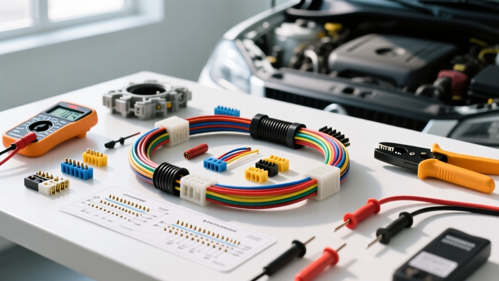
Executing a proper transmission wiring harness repair requires specialized electrical tools. Standard test lights will backfeed voltage and destroy sensitive PCM driver transistors. Equip your bench with:
- DVOM with Min/Max Recording: Essential for capturing intermittent opens while manipulating the harness.
- Back-Probe Pins: T-pin style probes for testing sealed weather-pack and Metri-Pack connectors without damaging the terminal seals.
- Adhesive-Lined Heat Shrink & Solder Seal Splices: For external harness repairs requiring moisture and chemical resistance.
- Ratcheting Terminal Crimper: Specifically calibrated for Delphi Metri-Pack 280 or TE Connectivity AMP terminals (e.g., Delphi 12092118 or equivalent).
- TXL or GXL Automotive Wire: Cross-linked polyethylene insulated wire rated for high-temperature underhood and undercarriage environments.
Step-by-Step Transmission Wiring Harness Repair Flow
Step 1: Visual Inspection and Fluid Wicking Assessment
The most insidious failure mode in automatic transmission electrical systems is capillary fluid wicking. If the internal transmission connector seal fails, Automatic Transmission Fluid (ATF) can travel under the wire insulation, migrating via capillary action all the way up the harness and into the Powertrain Control Module (PCM) connector.
Action: Disconnect the main transmission bulkhead connector at the transmission case. Inspect the male and female terminals for the presence of red or brown fluid. If ATF is present in the external connector, you must trace the harness up to the PCM. If fluid has reached the PCM cavity, a simple transmission wiring harness repair will not suffice; the entire external harness and internal harness must be replaced, and the PCM connectors must be flushed with specialized electronic contact cleaner to prevent internal board corrosion.
Step 2: Internal Harness and Solenoid Resistance Testing
If fluid intrusion is ruled out, isolate the internal harness. Drain the fluid, remove the transmission pan, and locate the internal bulkhead connector where the internal harness mates to the case pass-through.
Action: Disconnect the internal harness from the case connector. Set your DVOM to the Ohms (Ω) setting. Probe the terminals corresponding to the suspect circuit. For example, on a GM 4L60E, Shift Solenoid A (SSA) should read between 20-30 ohms at 68°F (20°C). If the DVOM reads 'OL' (Open Loop), the fault lies in the internal harness or the solenoid coil itself. Visually inspect the internal harness routing; it is common for the harness to rub against the valve body separator plate or the filter neck, wearing through the 18 AWG wire insulation and causing a short-to-ground on the aluminum case.
Step 3: External Harness Continuity and Chafe Testing
The external harness is subjected to extreme thermal cycling, road debris, and vibration. The most common failure point is where the harness routes over the bellhousing or near the exhaust manifold.
Action: Disconnect the harness at both the transmission and the PCM. Perform a continuity test on the control circuits. Next, perform a short-to-ground test by connecting one DVOM lead to a known good chassis ground and the other lead to the suspect wire pin. Wiggle the harness aggressively along its entire length, paying special attention to factory retaining clips and loom ends. If the meter beeps or resistance drops below 100 ohms, you have located a chafe point. Mark the area with painter's tape for repair.
Step 4: Execution of the Transmission Wiring Harness Repair
Never use twist-and-tape methods or standard vinyl electrical tape for undercarriage harness repairs. The environment demands chemical resistance against ATF, brake cleaner, and road salt, alongside high-temperature tolerance.
Action: Cut out the damaged section of the wire. Strip back 3/8 inch of insulation using precision wire strippers to avoid nicking the copper strands. Select a matching gauge of TXL wire (typically 18 AWG for solenoids, 14 AWG for power feeds). Insert the wires into a solder-seal splice connector. Apply heat evenly with a heat gun until the solder ring melts and flows into the wire strands, and the adhesive lining extrudes slightly from the ends. This creates a hermetic, waterproof seal. Finally, wrap the repaired section in split loom and secure it with high-temperature Tesa tape, ensuring the harness is routed away from sharp casting edges and heat sources.
GM 4L60E / 4L65E 16-Way Transmission Connector Pinout
When performing a transmission wiring harness repair on GM longitudinal applications, referencing the exact pinout and wire specifications is critical to avoid cross-circuit misfires. Below is the standard 16-way Metri-Pack connector specification.
| Pin | Circuit Function | Standard Wire Color | AWG | Diagnostic Note |
|---|---|---|---|---|
| A | Ignition 1 Voltage | Pink | 14 | Main power feed for solenoids. Check for voltage drop. |
| B | Ground | Black/White | 14 | Must have less than 0.1V drop to battery negative. |
| C | Shift Solenoid A (SSA) | Yellow | 18 | PCM provides ground to energize. 20-30 Ohms. |
| D | Shift Solenoid B (SSB) | Light Green | 18 | PCM provides ground to energize. 20-30 Ohms. |
| E | TCC PWM Solenoid | Tan/Black | 18 | High failure rate due to heat. Check for chafing. |
| F | 3-2 Shift Solenoid | Brown | 18 | Controls downshift flare. Rarely fails internally. |
| G | Line Pressure Control (PC) | Light Blue/Black | 18 | Variable force solenoid. 3-10 Ohms. Do not apply 12V directly. |
| H | Transmission Fluid Temp (TFT) | Yellow/Black | 18 | Thermistor signal. Resistance drops as temp rises. |
| J | TFT Sensor Ground | Black | 18 | Dedicated sensor ground back to PCM. |
| K | Input Speed Sensor (ISS) High | White | 20 | Shielded twisted pair. Check for AC voltage while cranking. |
| L | Input Speed Sensor (ISS) Low | White/Black | 20 | Shielded twisted pair. Must not be shorted to chassis. |
| M | Output Speed Sensor (OSS) High | Purple | 20 | Shielded twisted pair. Verify gap to reluctor ring. |
| N | Output Speed Sensor (OSS) Low | Purple/White | 20 | Shielded twisted pair. |
| P | Pressure Switch Signal | Gray | 18 | TFP switch assembly. Verify continuity in manual 1st. |
When to Abandon Repair and Install a Replacement Harness Kit
While a targeted transmission wiring harness repair is cost-effective for isolated chafes or broken pins, certain conditions mandate a full replacement harness kit. According to diagnostic guidelines shared by the International Automotive Technicians Network (iATN), if the internal harness exhibits widespread insulation flaking (often described as 'cracking like dry leaves'), attempting to tape or heat-shrink individual wires will only delay inevitable failure. The vibration of the transmission case will quickly shatter adjacent brittle insulation.
Furthermore, if the bulkhead connector plastic housing is warped from excessive heat, or if the terminal retention tangs are broken, no amount of wire repair will solve the intermittent connection issue. In these scenarios, sourcing an OEM or high-quality aftermarket replacement harness kit—complete with pre-crimped terminals and sealed bulkhead pass-throughs—is the only repair that meets SAE J1128 standards for underhood and undercarriage wiring durability. Always reference official GM Service Information (GMSI) or equivalent manufacturer documentation to ensure proper harness routing and torque specifications for retaining bolts, as improper tension can lead to premature connector failure.