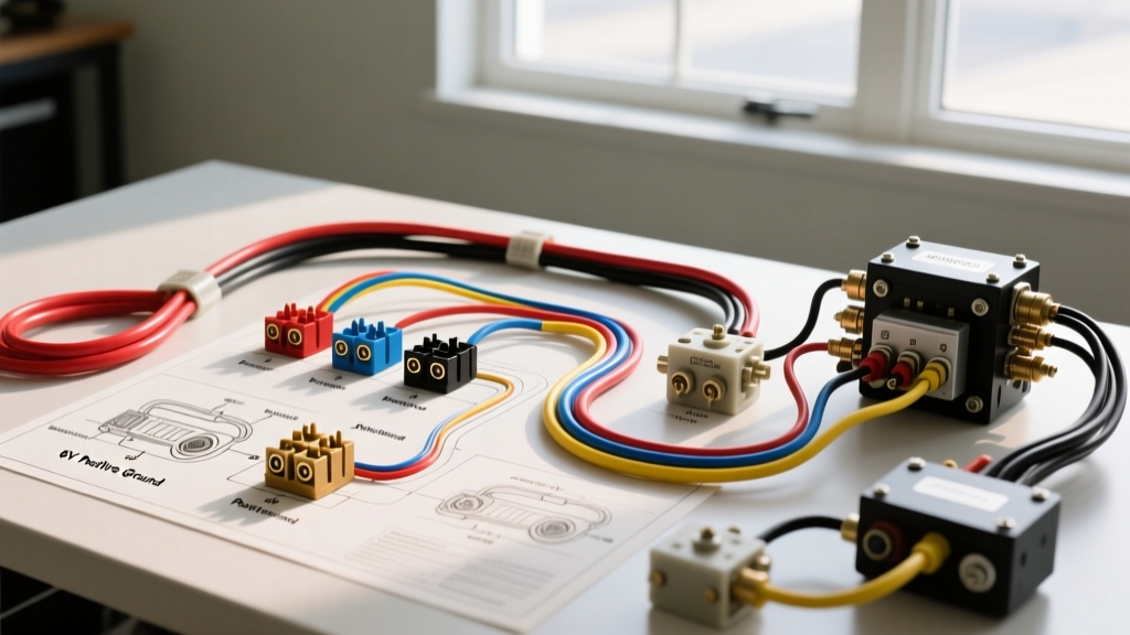
Introduction to Model A Electrical Architecture
When analyzing a wiring diagram Model A Ford system, restorers and technicians must bridge a century of automotive evolution. Produced between 1927 and 1931, the Ford Model A represented a massive leap forward from the Model T, introducing a conventional sliding-gear transmission, four-wheel mechanical brakes, and a comprehensive, battery-driven electrical system. Unlike modern vehicles governed by complex PCM networks and CAN-bus architecture, the Model A relies on a raw, unregulated, and highly mechanical electrical architecture. Understanding the original 6-volt positive ground schematic—and the nuances of modern 12-volt conversions—is critical for safe, reliable operation and accurate historical restoration.
Decoding the Original 6-Volt Positive Ground System
The factory electrical system of the Model A is a 6-volt, positive-ground configuration. In a positive-ground system, the positive terminal of the 3-cell lead-acid battery is physically bolted to the steel chassis frame, while the negative terminal routes to the starter switch and main harness. Early automotive engineers favored positive grounding because it was believed to reduce galvanic corrosion on the chassis; when the chassis acts as the positive anode, it corrodes slower than if it were the negative cathode in the electrochemical reaction with the earth and moisture.
Generator and Cutout Relay Mechanics
Unlike modern alternators with solid-state internal voltage regulators, the Model A utilizes a shunt-wound DC generator equipped with a third-brush adjustment mechanism to limit maximum output (typically set to 40 amps). The generator is paired with a mechanical cutout relay. This electromagnetic switch monitors the voltage differential between the generator and the battery. When the engine RPM increases and generator output exceeds the battery's resting voltage (approximately 6.3V to 6.6V), the voltage coil energizes, pulling the contact points closed to charge the battery. If the points weld shut due to arcing, the battery will back-feed into the generator at idle, motorizing it and potentially destroying the armature. According to the Model A Ford Club of America (MAFCA), regular inspection and filing of the cutout relay points is a mandatory maintenance interval for 6-volt purists.
Ignition and Distributor Specifications
The Model A ignition system relies on a 6-volt coil and a points-style distributor. A unique feature of the Model A distributor is that the condenser is housed internally within the distributor body, rather than externally on the coil bracket as seen in later flathead V8s. The lower breaker plate is grounded directly to the distributor housing. Proper points gap is critical; it must be set precisely to 0.018–0.022 inches. An incorrect gap alters the dwell angle, leading to insufficient coil saturation at low RPMs or severe point arcing at high RPMs, which will rapidly burn the tungsten contacts.
Wire Gauge, Insulation, and Routing Specifications
Original Model A wiring utilized copper strands insulated with vulcanized rubber and wrapped in a cotton-braid loom. Over decades, this rubber becomes brittle, cracks, and causes dead shorts against the steel chassis. Modern restorations mandate the use of cross-linked polyethylene (XLPE) insulated wire, specifically GXL or TXL types, which meet the SAE J1128 Low Tension Primary Cable Standard. GXL offers standard wall thickness for durability, while TXL features thin-wall insulation for tighter harness wrapping. For concours-correct restorations, modern GXL wire is often sleeved in authentic-looking waxed cotton braid.
| Circuit Function | AWG Size | Original Insulation | Modern GXL/TXL Color Code | Max Continuous Draw |
|---|---|---|---|---|
| Battery to Starter Switch | 1/0 AWG | Rubber / Cotton Braid | Black (Red for 12V Negative Ground) | 250+ Amps (Cranking Surge) |
| Battery to Ammeter | 10 AWG | Rubber / Cotton Braid | Black | 40 Amps |
| Ammeter to Ignition Switch | 14 AWG | Rubber / Cotton Braid | Red | 4 Amps |
| Horn Circuit (Main Feed) | 14 AWG | Rubber / Cotton Braid | Yellow | 12 Amps |
| Main Lighting Harness | 12 AWG | Rubber / Cotton Braid | Blue / Green Tracer | 20 Amps |
Terminal connections on the Model A originally relied on soldered lugs or specific Ford barrel crimps. Today, best practices dictate the use of closed-barrel crimp terminals sealed with dual-wall, adhesive-lined heat shrink. This prevents capillary action from drawing moisture and road salt into the copper strands, a common failure mode discussed extensively on The Ford Barn Electrical Forums.
12-Volt Negative Ground Conversion Schematics
While purists maintain the 6-volt positive ground system, many daily-driven Model A owners opt for a 12-volt negative ground conversion. This upgrade provides significantly faster cranking speeds, brighter halogen or LED lighting, and the ability to run modern accessories like 12V USB chargers or electronic fuel pumps. However, converting the wiring diagram requires systematic component upgrades to prevent catastrophic electrical fires or component burnout.
Component Upgrades and Resistor Requirements
- Ignition Coil Ballast Resistor: A standard 6-volt coil will overheat and boil its internal dielectric oil if fed 14.4 volts from a 12-volt alternator. You must install a 1.5-ohm to 3.0-ohm ceramic ballast resistor in series between the ignition switch and the positive terminal of the coil.
- Ammeter Reversal: The Model A ammeter is a series-wired gauge. When switching from positive ground to negative ground, the current flows through the gauge in the opposite direction. To prevent the needle from pegging into the negative discharge zone while charging, the two posts on the back of the ammeter must be swapped.
- Wiper and Heater Motors: If the vehicle is equipped with an aftermarket 6-volt electric windshield wiper or heater fan, these motors will spin at destructive speeds on 12 volts. They must be replaced with 12-volt equivalents or wired through a high-wattage dropping resistor.
- Generator vs. Alternator: Pragmatists often install a 1-wire Delco 10-SI alternator, requiring a custom bracket and a charge wire routed directly to the starter solenoid. Purists prefer a 12-volt internally regulated generator, which retains the original cutout relay appearance while providing reliable 14-volt output.
Advanced Troubleshooting: Voltage Drop and Grounding
The most pervasive issue in Model A electrical systems is not a failure of the components, but a failure of the grounds. Because the vehicle relies on the steel chassis and body tub to complete the circuit back to the battery, rust, paint, and rubber body mounts create massive electrical resistance.
The Voltage Drop Test in 6V Systems
Ohm's Law dictates that resistance causes a voltage drop. In a 12-volt system, a 0.6-volt drop across a corroded ground strap represents a 5% loss, which most components can tolerate. In a 6-volt system, a 0.6-volt drop is a 10% loss, resulting in noticeably dim headlights and sluggish starter cranking. To diagnose this, use a digital multimeter (DMM) set to DC Volts. Place the positive probe directly on the battery's ground post and the negative probe on the metal housing of the headlight bucket. Turn the headlights on. A reading higher than 0.2 volts indicates severe chassis resistance. The fix requires installing heavy-duty braided copper grounding straps from the engine block to the chassis frame, and from the chassis frame to the firewall and body tub, ensuring all contact points are sanded down to bare, shiny metal.
Horn Circuit and Steering Wheel Ground Ring
The Model A horn circuit is completed when the driver presses the horn button on the steering wheel, which grounds the circuit through the steering column. Over time, the brass ground ring inside the steering box wears out or becomes coated in dielectric grease, resulting in a dead horn. Troubleshooting requires verifying continuity from the horn button wire to the steering column housing, and ensuring the horn relay (if equipped with a modern high-amperage horn) is receiving a clean 6V or 12V feed directly from the battery via an inline 15-amp fuse.