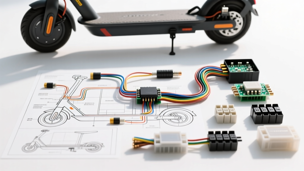
Decoding the 48 Volt Electric Scooter Wiring Diagram Owner's Manual
When troubleshooting a high-performance e-bike, referencing the 48 volt electric scooter wiring diagram owner's manual is only the first step. Factory schematics provided in these manuals often rely on generic IEC (International Electrotechnical Commission) symbols that obscure the physical reality of the harness. For instance, a simple rectangular symbol labeled "R" in the manual might represent the internal shunt resistor of the BLDC (Brushless DC) motor controller, while a series of diodes represents the MOSFET bridge. Understanding these schematic translations is critical before purchasing replacement parts or attempting a custom rewire.
A standard 48V nominal system actually operates at 54.6V fully charged and can experience back-EMF (Electromotive Force) voltage spikes exceeding 75V during aggressive regenerative braking or sudden throttle cuts. Therefore, the tools and materials required to service these systems must exceed standard 12V automotive specifications. This analysis breaks down the exact diagnostic tooling, wire gauge requirements, and cost structures needed to properly execute repairs based on your OEM manual.
Essential Tool Requirements for 48V Schematic Diagnostics
Reading the diagram is useless if you cannot accurately verify the signals. Standard automotive test lights and cheap multimeters will fail to read the 16kHz PWM (Pulse Width Modulation) signals sent from the controller to the hub motor, and they pose a severe safety risk when measuring high-amperage lithium-ion battery packs.
Diagnostic Equipment Checklist
- True-RMS Digital Multimeter (CAT III 600V rated): Required to accurately measure the DC bus voltage and the RMS value of the PWM phase signals. A low-pass filter function is highly recommended to prevent high-frequency motor noise from skewing voltage readings.
- Digital Storage Oscilloscope (DSO): Essential for analyzing the 5V square-wave signals from the Hall effect sensors inside the hub motor. A DSO will instantly reveal if a Hall sensor is failing due to signal dropout or electromagnetic interference (EMI).
- Ratcheting Wire Crimper (SN-48B or equivalent): For terminating JST-SM and Higo/ZWP waterproof connectors. Hand-crimping 22 AWG signal wires without a ratcheting mechanism leads to micro-fractures that fail under steering stem vibration.
- Temperature-Controlled Soldering Station: Required for tinning 8 AWG and 10 AWG silicone battery leads before inserting them into XT90 or Anderson SB50 housings.
| Tool Category | Specification / Standard | Estimated Cost (USD) | Justification |
|---|---|---|---|
| True-RMS Multimeter | CAT III 600V, True-RMS | $250 - $400 | Accurate PWM and DC bus measurement; prevents meter explosion from voltage spikes. |
| Ratcheting Crimper | AWG 28-18, JST/Higo profiles | $45 - $85 | Ensures IPC/WHMA-A-620 compliant crimps for signal wires. |
| Soldering Station | 60W+ with chisel tips | $110 - $150 | High thermal mass required to flow solder on 8 AWG tinned copper strands. |
| Adhesive Heat Shrink | 3M Dual-Wall, 3:1 ratio | $35 - $50 | Waterproofs battery connections against road spray and condensation. |
| Total Toolkit | $440 - $685 | One-time investment for professional-grade 48V EV diagnostics. |
Wire Gauge (AWG), Color Codes, and Connector Specifications
The 48 volt electric scooter wiring diagram owner's manual will typically outline wire colors, but OEM manufacturers frequently change suppliers, resulting in color deviations. Always verify continuity with a multimeter rather than trusting the insulation color blindly. Furthermore, wire material is critical. You must use high-strand-count silicone wire (UL3135 standard) for the main battery and phase lines. Standard PVC automotive wire (UL1007) becomes brittle under the constant flexing of the scooter's steering column and suspension.
| Circuit Function | Standard Wire Color | AWG Size | Wire Type | Connector Type |
|---|---|---|---|---|
| Battery Main (+) | Red | 8 AWG | UL3135 Silicone | Anderson Power SB50 or XT90 |
| Battery Main (-) | Black | 8 AWG | UL3135 Silicone | Anderson Power SB50 or XT90 |
| Motor Phase A | Yellow | 12 AWG | UL3135 Silicone | 4.5mm Gold Bullet (Male/Female) |
| Motor Phase B | Green | 12 AWG | UL3135 Silicone | 4.5mm Gold Bullet |
| Motor Phase C | Blue | 12 AWG | UL3135 Silicone | 4.5mm Gold Bullet |
| Hall Sensor VCC/GND | Red / Black | 22 AWG | UL1007 PVC | JST-SM 5-Pin or Higo ZWP |
| Hall Signals (A/B/C) | Yel / Grn / Blu | 22 AWG | UL1007 PVC | JST-SM 5-Pin or Higo ZWP |
| Throttle Signal | White / Green | 24 AWG | UL1007 PVC | JST-SM 3-Pin |
Terminal Torque and Crimping Standards
When terminating 8 AWG battery wires with M5 or M6 ring terminals for the BMS (Battery Management System) or main contactor, torque specifications are vital. Under-torqued terminals create high-resistance joints that generate heat, melting the XT90 connector housing. M5 ring terminals on copper busbars should be torqued to 3.0 - 4.0 Nm, while M6 terminals require 5.0 - 6.0 Nm. Always use a star washer between the ring terminal and the busbar to bite through oxidation and ensure a low-resistance connection, adhering to the principles outlined in SAE J1128 for battery cable terminations.
Cost Analysis: OEM Harness Replacement vs. Custom Rewiring
When the wiring diagram reveals a melted harness or a shorted controller, technicians and DIYers face a choice: buy the OEM replacement harness or build a custom one. OEM harnesses for 48V scooters (like those from Kaabo, Dualtron, or Vsett) are often overpriced and suffer from long international shipping times. Building a custom harness using bulk silicone wire and high-quality connectors is often cheaper and results in a more durable, flexible setup.
Itemized Cost Breakdown: Custom 48V Harness Build
- 8 AWG Silicone Wire (10 ft, Red/Black): $28.00 (Handles up to 60A continuous, 120A burst)
- 12 AWG Silicone Wire (15 ft, RGB): $22.00 (For motor phase lines)
- 22 AWG Signal Wire (20 ft, Multi-color): $12.00 (For Hall sensors and throttle)
- Anderson SB50 Connector Kit: $18.00 (Superior to XT90 for frequent battery disconnects)
- 4.5mm Bullet Connectors (12 AWG): $8.00
- JST-SM Connector Kit with Pins: $10.00
- Tesa Harness Tape & Adhesive Heat Shrink: $25.00
- Total Material Cost: ~$123.00
Comparison: A direct OEM replacement harness from a major importer typically retails for $165.00 to $220.00, excluding shipping. The custom route saves roughly $70 and allows you to upgrade the main battery connectors from failure-prone XT60s to heavy-duty Anderson SB50s.
Common Failure Modes in 48V Scooter Wiring
Understanding the schematic allows you to predict where the system will fail. The most common issues in 48V electric scooters are not the battery cells themselves, but the interconnects and signal wires.
1. Phase Wire Arcing and Melt-Downs
The BLDC motor requires massive current (often 40A to 80A peak) through the 12 AWG phase wires. If the 4.5mm bullet connectors are not fully seated, or if they lack adequate heat shrink, moisture ingress causes oxidation. This increases resistance, leading to localized heating that melts the silicone insulation and shorts the three phases together, instantly destroying the controller's MOSFET bridge.
2. Hall Sensor Ground Loops
The owner's manual wiring diagram will show the Hall sensor ground returning directly to the controller's 5V logic ground. In many cheap aftermarket wiring harnesses, this ground is shared with high-draw accessories like LED headlights or horns. When the headlight cycles, it induces a voltage drop on the shared ground wire. The controller misinterprets this ground shift as a false Hall sensor signal, causing the motor to stutter, cog, or throw an Error Code 07 (Hall Sensor Fault). The fix is to run a dedicated 22 AWG ground wire directly from the motor Hall connector to the controller's logic ground pin.
3. Ignition Switch Voltage Drop
The ignition switch on a 48V scooter does not carry the main motor current; it only triggers the controller's logic circuit and powers the DC-DC converter. However, OEM switches are often rated for only 2A. If a user adds a 48V-to-12V DC-DC converter to run 50W of auxiliary lighting, the ignition switch will overheat and melt internally. Upgrading the ignition circuit to use a 48V-rated automotive relay, triggered by the low-amp OEM switch, is a mandatory modification for any scooter running auxiliary loads.