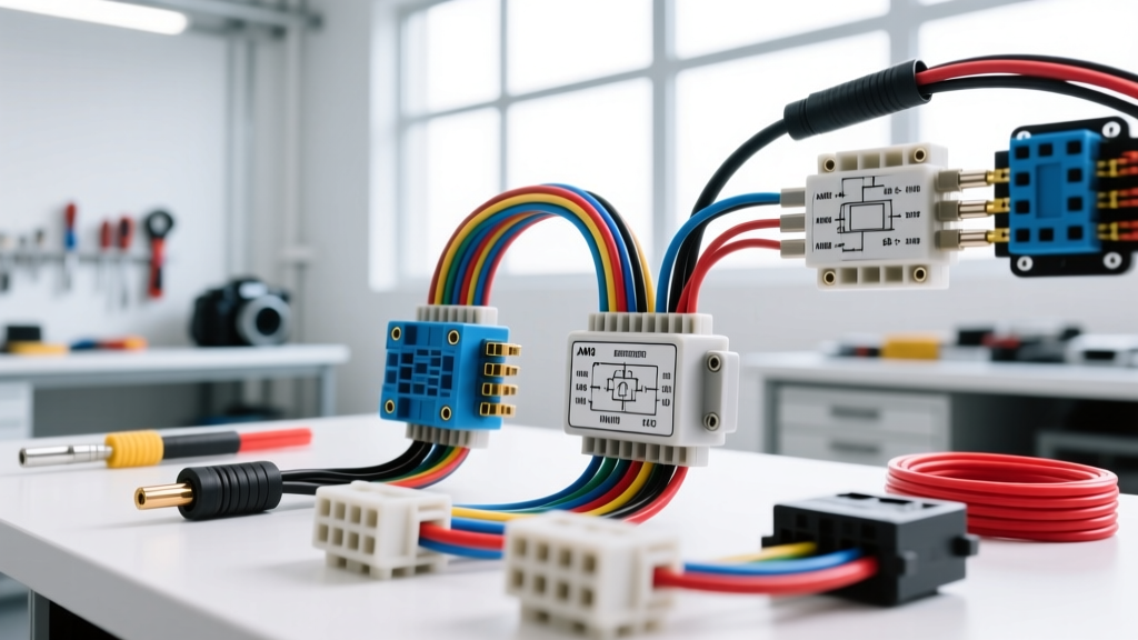
Why Document Your Custom Automotive Wiring?
Whether you are building a restomod, wiring auxiliary off-road lighting, or fabricating a custom engine harness for an LS swap, relying on mental notes is a recipe for parasitic draws, melted insulation, and electrical fires. Learning how to create wiring diagram online free using modern browser-based tools empowers DIYers and professional fabricators to map out complex circuits before cutting a single zip tie.
Proper documentation bridges the gap between a chaotic nest of wires and a reliable, serviceable vehicle electrical system. In this beginner-friendly guide, we will explore the best free schematic software, translate physical automotive components into standardized symbols, and review the critical SAE standards that govern wire sizing and color codes.
Top Platforms to Create Wiring Diagram Online Free
When mapping vehicle-specific schematics, you need software that supports standard electrical symbols (IEEE/IEC) and allows for easy annotation of wire gauges and pinouts. Here are the top free, browser-based tools for automotive electricians:
- diagrams.net (formerly Draw.io): The most versatile free tool. It features extensive electrical engineering shape libraries, allows you to create custom wire harness connectors, and exports to high-resolution PDFs for printing and laminating to keep in the glovebox.
- CircuitLab: Excellent for simulating basic DC circuits. While the free tier has limitations, it is perfect for calculating voltage drops across long wire runs to your fuel pump or cooling fans.
- EasyEDA: Primarily for PCB design, but its schematic capture tool is highly robust for mapping out custom fuse boxes and relay logic boards.
Automotive Wiring Fundamentals: SAE J1128 and Wire Sizing
Before you drag and drop components onto your digital canvas, you must understand the physical properties of automotive wire. The SAE J1128 standard dictates the requirements for low-tension primary cables used in road vehicles. This includes insulation thickness, temperature resistance, and current-carrying capacity.
When you create your schematic, every wire line must be labeled with its AWG (American Wire Gauge) size and color code. Below is a fundamental reference chart for common automotive circuits:
| AWG Size | Approx. Metric | Max Continuous Amps | Common Automotive Application | Standard Fuse Rating |
|---|---|---|---|---|
| 18 AWG | 0.8 mm² | 6 Amps | ECU sensors, low-draw LEDs, radio memory | 5A - 7.5A |
| 14 AWG | 2.0 mm² | 15 Amps | Tail lights, interior dome lights, horn trigger | 15A |
| 12 AWG | 3.0 mm² | 20 Amps | Fuel pumps, power windows, windshield wipers | 20A |
| 10 AWG | 5.0 mm² | 30 Amps | Radiator cooling fans, main ignition feeds | 30A |
| 8 AWG | 8.0 mm² | 40 Amps | High-draw winches, main battery to alternator | 40A - 50A |
Standardizing Wire Colors in Your Schematic
While custom harness builders often use their own color palettes, adhering to industry conventions makes troubleshooting drastically easier. Standard automotive color codes include:
- Red: Constant 12V+ Battery Power (unfused or pre-fuse)
- Black: Chassis Ground
- Yellow: Switched 12V+ (Ignition or Accessory)
- Blue: Low-current signals, ECU triggers, or CAN bus lines
- Orange: Illumination circuits or variable voltage dash feeds
Mapping Relays and Fuses: The ISO Mini Relay
The most common component you will map when designing custom lighting, fuel systems, or cooling circuits is the standard Bosch-style ISO mini relay. Understanding its pinout is mandatory for accurate schematic creation. According to MAD Electrical's automotive relay guide, miswiring the control and load circuits is the number one cause of melted harnesses in DIY builds.
Standard 5-Pin ISO Relay Pinout Reference
- Pin 30 (Power In): Connects directly to the battery positive via a main fuse. Use 10 AWG or 12 AWG wire depending on the load.
- Pin 87 (Power Out - NO): Normally Open. Feeds power to the load (e.g., fuel pump, headlights) when the relay is energized.
- Pin 87a (Power Out - NC): Normally Closed. Feeds power when the relay is OFF. Rarely used in basic automotive builds but common in alarm kill-switch circuits.
- Pin 86 (Coil +): Receives the switched 12V+ trigger signal from the dashboard switch or ECU. Use 18 AWG or 16 AWG wire.
- Pin 85 (Coil -): Connects to a clean, bare-metal chassis ground.
Expert Tip: If your relay coil is being triggered directly by an ECU driver (like a modern engine management system controlling a fuel pump relay), you must include a flyback diode across pins 85 and 86 in your schematic. This prevents the inductive voltage spike from frying the ECU's internal transistor when the relay de-energizes.
Step-by-Step: Drafting a Headlight Relay Circuit
Let us apply these fundamentals to create a practical schematic using your chosen free online tool. We will map a high-current headlight upgrade utilizing a standard Weather-Pack connector setup.
- Establish Power and Ground Buses: Draw a horizontal line at the top of your canvas for 12V+ and a line at the bottom for Ground. Label the power source with a Mega Fuse or MAXI fuse rating (e.g., 40A).
- Place the Relay: Insert a 5-pin relay symbol. Route Pin 30 to the 12V+ bus. Route Pin 85 to the Ground bus.
- Map the Trigger Circuit: Connect Pin 86 to your headlight switch output. Insert an inline 5A ATO blade fuse on this 18 AWG trigger wire to protect the factory switch.
- Route the Load Circuit: Connect Pin 87 to the positive terminal of your new HID or LED headlight ballasts. Label this line as 12 AWG.
- Specify Connectors: Add notes indicating the use of 2-pin Weather-Pack sealed connectors at the headlight housings to prevent moisture ingress and corrosion.
Specifying Connectors: Weather-Pack vs. Metri-Pack
When annotating your schematic, specify the exact connector family. The Delphi (Aptiv) Weather-Pack series is ideal for high-current, harsh-environment connections like cooling fan pigtails and trailer plugs, utilizing large silicone seals and 20-12 AWG terminals. For modern sensor wiring, ECU pins, and interior cabin connections, the Metri-Pack 150 or 280 series is the industry standard, offering a smaller footprint and superior terminal retention for 22-14 AWG wires. Noting these on your diagram ensures you order the correct crimp dies and seal plugs.
Common Beginner Mistakes to Avoid in Schematics
When using free software to create wiring diagram online free layouts, beginners often focus on the logic but forget the physical realities of the vehicle environment.
- Ignoring Voltage Drop: A wire might be rated for 20 amps, but if it is 15 feet long, the resistance will cause a significant voltage drop. Your schematic should note long runs that require stepping up one AWG size (e.g., using 10 AWG instead of 12 AWG for a distant fuel pump).
- Floating Grounds: Never daisy-chain grounds on a schematic. Every major component should have a dedicated ground path back to a central grounding bus or the battery negative terminal, utilizing ring terminals and star washers on bare metal.
- Omitting Connector Types: A schematic that only shows lines is useless during assembly. Always annotate whether a connection is a solder joint, a crimped butt splice, a Metri-Pack 150 series terminal, or a Deutsch DT plug.
Advanced Troubleshooting: Parasitic Draws and Voltage Drops
Once your harness is built and installed, the digital schematic becomes your primary diagnostic tool. If a circuit fails, use a digital multimeter to perform a voltage drop test. According to Fluke's electrical testing guidelines, a healthy automotive circuit should have less than 0.1V drop across any single connection or fuse, and less than 0.2V drop across the ground path. By following your printed schematic, you can probe at specific nodes to isolate exactly where the resistance is occurring.
Furthermore, your schematic is vital for diagnosing parasitic draws. If your battery dies overnight, pull the fuses one by one while monitoring the amperage at the battery negative terminal. Once the draw drops below 50 milliamps, consult your schematic to see exactly which modules or relays (like a stuck fuel pump relay or an aftermarket stereo memory wire) are tied to that specific fuse cavity.
Conclusion
Taking the time to create wiring diagram online free layouts before purchasing wire and terminals is the hallmark of a professional automotive electrician. By combining accessible digital tools with strict adherence to SAE J1128 wire standards, proper relay logic, and sealed connector practices, you ensure your custom vehicle build is safe, reliable, and easy to maintain for years to come.