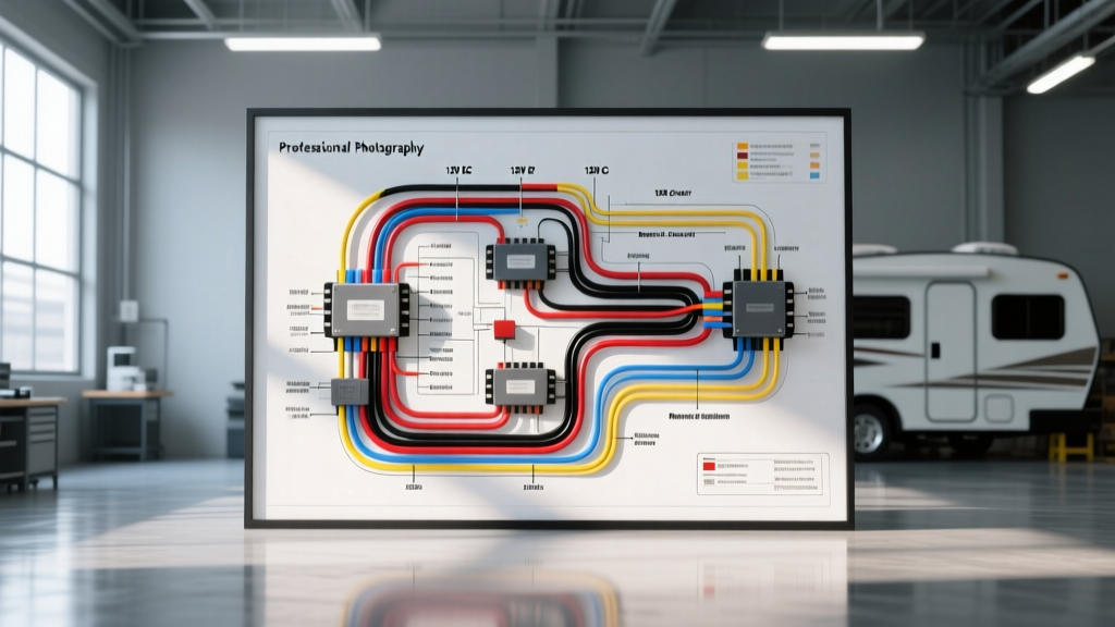
Understanding the RV Power Converter Architecture
When diagnosing electrical faults in a recreational vehicle, referencing an accurate wiring diagram for RV converter systems is critical. Unlike automotive alternators that generate DC power directly from the engine, an RV power converter (often integrated into a power distribution center) is a static solid-state device. It steps down 120V AC shore power or generator power to 12V-14.4V DC to operate coach loads (lights, water pumps, slide-out motors) while simultaneously charging the house battery bank. Because these units bridge high-voltage AC and low-voltage DC systems, troubleshooting requires a systematic, step-by-step flow to isolate the fault without risking damage to sensitive coach electronics or the battery bank.
Decoding the RV Converter Wiring Diagram
Before grabbing a multimeter, you must understand the color codes and routing specified in the wiring diagram for RV converter installations. A common trap for automotive technicians is assuming DC ground is black. In RV applications governed by NFPA 1192 standards, the DC wiring convention is strictly:
- Red: +12V DC Positive
- White: -12V DC Negative (Ground)
On the 120V AC input side, standard residential colors apply: Black (Hot/L1), White (Neutral), and Green or Bare (Equipment Ground). The AC input typically feeds from a dedicated 30A or 50A double-pole breaker in the main AC distribution panel via 10 AWG or 6 AWG THHN copper wire. The DC output routes through heavy-gauge stranded copper (usually 6 AWG or 4 AWG) to the DC fuse board and directly to the battery bank via a Class T or ANL fuse.
Step-by-Step Troubleshooting Flow
Use the following diagnostic flow to isolate failures based on the most common RV converter symptoms.
Symptom 1: Complete 12V DC Coach Failure (Lights Dead, Water Pump Fails)
Step 1: Verify AC Input Voltage
Set your digital multimeter (DMM) to AC Volts. Remove the converter's AC access cover and probe the L1 (Black) and Neutral (White) terminal block screws. You must read between 110V and 125V AC. If voltage is absent, the fault lies upstream in the AC breaker panel or shore power cord. If voltage is present, proceed to Step 2.
Step 2: Inspect the Reverse Polity Fuses
Locate the DC distribution board adjacent to the converter. Most modern units (like WFCO or Progressive Dynamics) feature two 30A or 40A ATO/ATC blade fuses labeled 'Reverse Polarity'. These fuses protect the converter if the battery is connected backward. Pull both fuses and test for continuity. If blown, replace them, but immediately check the battery terminals for reversed cables before reconnecting shore power, or the new fuses will instantly blow.
Step 3: Measure DC Output at the Bus Bar
Set the DMM to DC Volts. Probe the main DC positive bus bar and the negative bus bar. A healthy converter in 'Float' mode will read 13.2V. In 'Bulk' or 'Absorption' mode, it will read 13.6V to 14.4V. If the reading is 0V despite good AC input and intact fuses, the internal transformer or rectifier bridge has failed, requiring a complete converter replacement.
Symptom 2: 120V AC Works, but House Battery Fails to Charge
Step 1: Check for Voltage Drop on the Charge Line
If the coach lights work but the battery drains over time, the converter may not be reaching the battery. Probe the DC voltage at the converter's output terminals, then probe directly at the battery posts. If you read 13.6V at the converter but only 12.2V at the battery, you have a severe voltage drop. This is usually caused by undersized wiring (e.g., using 8 AWG instead of 4 AWG for a long run) or heavy corrosion on the battery lugs.
Step 2: Force the Converter into Bulk Mode
Modern smart converters use a 3-stage charging algorithm. If the battery voltage is above 12.6V, the converter drops to a 13.2V 'Float' mode, which barely provides enough amperage to charge a depleted deep-cycle battery. Consult your specific wiring diagram for RV converter mode-switching. For example, Progressive Dynamics units often use a 'Charge Wizard' pendant switch, while WFCO units may use a physical dip-switch on the control board to force 14.4V Bulk charging. If forcing Bulk mode yields no amperage flow (verified via a DC clamp meter on the positive battery cable), the battery cells may be sulfated or shorted.
Symptom 3: Converter Emits Loud Buzzing or Cycles Fan Erratically
Step 1: Inspect the Cooling Fan and Thermistor
Converters generate significant heat during Bulk charging. A PWM-controlled cooling fan should engage when internal temperatures reach 104°F (40°C). If the fan is seized or the thermistor wiring (usually thin 18 AWG wires routed to the heat sink) is pinched, the converter will enter thermal protection mode, aggressively cycling power to prevent a meltdown. Clean the fan vents with compressed air and verify 12V DC is reaching the fan motor pins when the unit is warm.
Step 2: Check for AC Ripple
Wire Gauge, Torque, and Routing Specifications
Adhering to the correct specifications when replacing or repairing wiring based on your wiring diagram for RV converter systems is vital for fire prevention and optimal performance.
| Circuit Path | AWG Size (Copper) | Max Recommended Length | Terminal Torque Spec |
|---|---|---|---|
| 120V AC Input (30A Service) | 10 AWG THHN Solid/Stranded | 25 ft | 12-14 in-lbs |
| 12V DC Main Output (to Fuse Board) | 6 AWG Stranded | 10 ft | 35-45 in-lbs |
| 12V DC Battery Charge Line | 4 AWG Stranded | 15 ft | 45-55 in-lbs |
| Chassis Ground Bonding | 8 AWG Stranded | 5 ft | 30-40 in-lbs |
Common Failure Modes and RVIA Code Compliance
One of the most frequent failure modes in RV distribution panels is thermal fatigue on the DC terminal blocks. The high-amperage DC output (often 45A to 65A continuous) generates heat. If the ring terminals are crimped improperly or torqued below the manufacturer's specification, the increased resistance creates a localized hot spot. Over time, this melts the plastic terminal block housing. Always use a calibrated torque screwdriver and inspect for heat discoloration on the white DC negative wires.
Furthermore, the Recreational Vehicle Industry Association (RVIA) and NFPA 1192 mandate specific grounding rules. The DC negative (White) must be bonded to the RV chassis at a single, centralized point—usually the main distribution panel bus bar. The converter's metal chassis must be bonded to the AC equipment ground (Green), but the DC negative must not be grounded directly to the converter's mounting screws. Doing so creates a ground loop, leading to erratic sensor readings and accelerated galvanic corrosion on the RV frame.