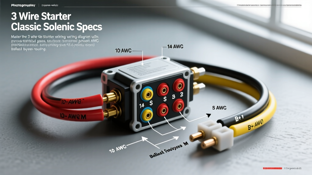
Technical Overview: The 3-Terminal Starter Solenoid
When restoring classic muscle cars, vintage trucks, or agricultural equipment equipped with points-style ignition systems, understanding the 3 wire starter wiring diagram is critical. Unlike modern vehicles utilizing high-energy ignition (HEI) or coil-on-plug (COP) systems that only require a two-wire starter connection (Battery and Signal), older platforms rely on a three-terminal solenoid configuration. This third wire is essential for bypassing the ignition ballast resistor during the cranking cycle, ensuring the ignition coil receives a full 12 volts to generate a strong spark while the starter motor draws heavy amperage.
The most common application for this 3 wire starter setup is the classic Delco Remy 10MT and 12MT gear-reduction and direct-drive starters found in millions of GM V8 applications from the 1960s through the 1980s. This technical specification reference details the exact terminal pinouts, AWG wire sizing, OEM color codes, and torque requirements required to execute this circuit flawlessly.
Terminal Identification & Wire Gauge Specifications
The starter-mounted solenoid features three primary external terminals. Misidentifying these terminals is the leading cause of no-crank conditions, melted ignition harnesses, and burnt-out ignition coils. Below is the definitive specification chart for the 3 wire starter solenoid.
| Terminal ID | Function | Recommended AWG | OEM Wire Color (GM) | Hardware / Torque Spec |
|---|---|---|---|---|
| BAT (B+) | Main Battery Power Feed | 4 AWG to 1/0 AWG | Red | 3/8" Nut, 90-110 in-lbs |
| S (Switch) | Solenoid Trigger (Pull-In Coil) | 10 AWG to 12 AWG | Purple | 10-32 Thread, 25-35 in-lbs |
| I / R (Ignition) | Ballast Resistor Bypass Feed | 14 AWG to 16 AWG | Yellow (or Resistance Wire) | 10-32 Thread, 25-35 in-lbs |
Circuit Routing: The 3 Wire Starter Wiring Diagram
To properly wire the system, you must route each circuit through the appropriate firewall grommets, neutral safety switches, and relays. The following breakdown outlines the exact path and electrical requirements for each of the three wires.
1. Main Battery Feed (BAT Terminal)
The BAT terminal provides the high-amperage current required by the starter motor (often exceeding 250 amps under load) and serves as the primary power distribution point for the vehicle's main harness.
- Wire Sizing: Use a minimum of 4 AWG stranded copper wire for runs under 6 feet. For engine bays with extended routing or high-compression engines requiring 1.5kW+ starters, upgrade to 2 AWG or 1/0 AWG to mitigate voltage drop.
- Termination: Use heavy-duty, heat-shrink-sealed copper ring terminals. Avoid cheap aluminum or tinned-iron lugs which introduce resistance and corrode rapidly.
- Routing: This cable must be routed away from exhaust manifolds and sharp engine block edges. Use split-loom tubing or braided firewall sleeves for protection.
2. Solenoid Trigger Circuit (S Terminal)
The 'S' terminal energizes the solenoid's pull-in and hold-in windings. When the ignition key is turned to 'START', 12V is sent to this terminal, pulling the heavy copper contact disc inside the solenoid to bridge the BAT and Motor terminals.
- Wire Sizing: 10 AWG or 12 AWG is standard. While the steady-state draw of the hold-in winding is low, the initial inrush current to the pull-in winding can spike to 15-20 amps.
- Safety Interlocks: This wire must route through the vehicle's Neutral Safety Switch (automatic) or Clutch Pedal Interlock Switch (manual) before reaching the ignition switch. According to SAE J1171 marine and automotive standards, all starter trigger circuits must incorporate a mechanical or electrical interrupt to prevent accidental engagement in gear.
- Connection: Secure the spade or ring terminal tightly. A loose 'S' terminal connection will cause high resistance, resulting in a rapid 'clicking' sound as the solenoid fails to fully engage the hold-in winding.
3. Ignition Ballast Bypass (I/R Terminal)
This is the defining wire of the 3 wire starter wiring diagram. Classic points-style ignitions use a ballast resistor (or a resistive wire in the harness) to drop the system voltage from ~14.2V (alternator output) down to ~9V for normal running conditions, protecting the ignition points from premature arcing and burning. However, during cranking, system voltage drops significantly. The 'I' terminal outputs a full 12V directly from the BAT terminal only while the solenoid is engaged, bypassing the resistor to give the coil maximum voltage for starting.
- Wire Sizing: 14 AWG to 16 AWG is sufficient, as it only powers the ignition coil primary winding.
- Routing: Connect this wire to the ignition coil side of the ballast resistor.
- CRITICAL WARNING: Never connect this wire to the main ignition harness feed. If back-fed, the solenoid will remain engaged even after the key is released from the 'START' position, destroying the starter motor and flywheel flexplate.
- HEI / Electronic Ignition Note: If the vehicle has been retrofitted with an HEI distributor, MSD, or EFI system, the 'I' terminal is not used. These systems require a full 12V at all times and utilize internal dwell control. Tape off and secure the 'I' wire to prevent shorting against the engine block.
Diagnostic Testing & Voltage Drop Thresholds
When troubleshooting a no-crank or slow-crank condition on a 3-wire system, rely on voltage drop testing rather than simple continuity checks. A wire with broken strands may show continuity on a multimeter but will fail under the 200+ amp load of a starter motor.
Testing the BAT Circuit
Set your digital multimeter to DC Volts. Place the red probe on the battery positive post (not the clamp) and the black probe on the starter BAT terminal. Have an assistant crank the engine. A reading greater than 0.2V indicates excessive resistance in the positive cable, terminals, or battery posts. Clean and retorque, or replace the 4 AWG cable.
Testing the Ground Return Path
Place the red probe on the starter motor housing (bare metal) and the black probe on the battery negative post. Crank the engine. A voltage drop exceeding 0.1V indicates a poor engine-to-chassis ground. Install a dedicated 2 AWG ground strap from the starter mounting bolt to the chassis frame rail to resolve this.
Testing the 'S' Terminal Trigger
Back-probe the 'S' terminal wire while an assistant holds the key in 'START'. You must see a minimum of 10.5V. If voltage is lower, inspect the bulkhead connector, ignition switch contacts, and neutral safety switch for corrosion or pitting. Installing a MSD Starter Solenoid Relay is a common technical fix for vintage vehicles suffering from voltage drop through the factory firewall harness.
Authoritative References & Standards
- Delco Remy Heavy Duty & Automotive Starter Service Manuals - Terminal torque specifications and internal winding resistance charts.
- SAE J1171: External Ignition Protected Starters - Guidelines on starter solenoid trigger circuit isolation and marine safety interlocks.
- Haynes Automotive Electrical Manual - Standardized wire gauge (AWG) ampacity charts and voltage drop testing procedures for 12V DC systems.