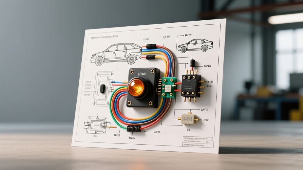
Understanding the 12V Rocker Switch with Pilot Light
When adding auxiliary off-road light bars, winch controls, or onboard air compressors to your truck or Jeep, a standard dashboard toggle simply will not suffice. You need a robust, weather-sealed interface. This is where understanding a wiring diagram for switch with pilot light configurations becomes essential. In automotive applications, a "pilot light" refers to the integrated LED indicator built directly into the rocker switch housing. This LED illuminates when the circuit is closed, providing immediate visual confirmation that your high-draw accessory is receiving power.
For beginners, the most critical fundamental to grasp is that you should never route high-amperage accessory power directly through the dashboard switch. While many aftermarket rocker switches are rated for 20 amps, running 15+ amps through the thin factory wiring harness of a modern vehicle will cause severe voltage drop, melted connectors, or an electrical fire. The correct approach utilizes a standard Bosch-style automotive relay. The switch with the pilot light will only handle the low-amperage "control" circuit, while the relay handles the heavy "load" circuit directly from the battery.
Anatomy of the Standard 5-Pin Automotive Rocker Switch
Most universal automotive and marine rocker switches (such as those from Blue Sea Systems or standard Carling-style imports) utilize a 5-pin or 3-pin SPST (Single Pole, Single Throw) design. For a switch featuring a single pilot light LED, you will typically use three specific terminals on the back of the switch housing.
| Pin Number | Terminal Label | Function | Recommended Wire Color |
|---|---|---|---|
| Pin 2 | +12V Source | Receives fused 12V ignition or constant power to feed the switch contacts and the internal LED. | Red (18 AWG) |
| Pin 3 | LED Ground | Completes the circuit for the internal pilot light LED. Must be tied to a clean chassis ground. | Black (18 AWG) |
| Pin 7 | Output / Load | Sends the +12V signal to the relay coil (Pin 86) only when the switch is rocked to the ON position. | Yellow (18 AWG) |
Note: Pin numbering can occasionally vary by manufacturer (some use Pin 6 instead of Pin 7 for the output). Always verify your specific switch's pinout using a digital multimeter set to the continuity (beep) setting before making permanent crimps.
Step-by-Step Wiring Diagram for Switch With Pilot Light (Relay Controlled)
To safely integrate your switch into the vehicle's electrical system, we will map out a standard 4-pin relay configuration. This setup ensures your auxiliary lights receive full battery voltage while keeping your dashboard wiring safe from high thermal loads.
1. The Control Circuit (Low Amp / Switch Side)
- Power Source: Run an 18 AWG Red wire from an ignition-switched fuse tap (if you want the accessory to turn off with the key) or directly from the battery via an inline 5A fuse. Connect this to Switch Pin 2.
- LED Ground: Connect an 18 AWG Black wire to Switch Pin 3. Route this to a verified, bare-metal chassis ground point near the dashboard. Use a ring terminal and a star washer to bite through paint and prevent galvanic corrosion.
- Relay Trigger: Connect an 18 AWG Yellow wire to Switch Pin 7. Route this through the firewall grommet to the engine bay and connect it to Relay Pin 86.
2. The Load Circuit (High Amp / Relay & Accessory Side)
- Relay Ground: Connect an 18 AWG Black wire to Relay Pin 85 and ground it securely to the vehicle chassis in the engine bay.
- Main Power Feed: Run a heavy-gauge wire (see AWG chart below) directly from the positive battery terminal. Install a waterproof fuse holder within 6 inches of the battery. Connect the other end to Relay Pin 30.
- Accessory Output: Connect the same heavy-gauge wire color from Relay Pin 87 directly to the positive input of your auxiliary light bar or compressor. The negative terminal of the accessory must be grounded to the chassis.
Wire Gauge (AWG) and Fuse Sizing Chart
One of the most common beginner mistakes is undersizing wire, which leads to resistance, heat buildup, and dim auxiliary lights. The SAE J1128 standard outlines strict guidelines for low-tension primary cables in automotive environments. Because engine bays exceed ambient room temperatures, you must use SAE-rated wire (which has thicker copper strands than standard AWG) and factor in voltage drop over distance.
| Total Accessory Wattage | Amperage Draw (at 13.8V) | Minimum SAE Wire Gauge (Up to 15ft) | Required Inline Fuse |
|---|---|---|---|
| 50W - 100W | 3.6A - 7.2A | 16 AWG | 10A |
| 120W - 200W | 8.6A - 14.4A | 14 AWG | 15A or 20A |
| 240W - 300W | 17.3A - 21.7A | 12 AWG | 25A or 30A |
| 360W - 500W | 26.0A - 36.2A | 10 AWG | 40A |
Termination and Environmental Protection
A wiring diagram for switch with pilot light setups is only as reliable as its physical connections. The under-hood environment is hostile, characterized by extreme thermal cycling, water ingress, and road salts. Never rely on electrical tape or bare crimp connectors.
For all connections, use adhesive-lined (dual-wall) heat shrink terminals. When heated, the inner thermoplastic adhesive melts and flows around the wire strands, creating a watertight seal that prevents capillary action from drawing moisture under the wire insulation. For firewall pass-throughs, always use existing rubber grommets; if you must pierce a new hole, use a dedicated rubber firewall grommet to prevent the sheet metal from slicing through the wire insulation and causing a dead short.
Common Beginner Mistakes and Troubleshooting
Even with a perfect schematic, physical installation errors can prevent the circuit from operating. Use this diagnostic tree if your pilot light fails to illuminate or the accessory does not engage.
Symptom: Switch Pilot Light Does Not Turn On
- Cause 1: Blown Control Fuse. Check the 5A inline fuse on the Red wire feeding Switch Pin 2.
- Cause 2: Poor LED Ground. The internal LED requires Pin 3 to be grounded. If you are using a multimeter, test for continuity between Pin 3 and the vehicle chassis. Clean away paint or rust at the grounding bolt.
- Cause 3: Reversed Polarity (Rare on incandescent, fatal on LED). While standard SPST switches are polarity agnostic for the main contacts, some integrated LEDs are diode-specific. Ensure Pin 2 is receiving positive voltage.
Symptom: Pilot Light Illuminates, Relay Clicks, But Accessory Has No Power
- Cause 1: Blown Main Fuse. The high-amp fuse near the battery (feeding Relay Pin 30) may have blown due to an inrush current spike from a compressor motor or shorted light bar.
- Cause 2: Voltage Drop on Load Side. Perform a voltage drop test across Relay Pin 30 and Pin 87 while the switch is ON. You should see less than 0.1V drop. A higher reading indicates corroded relay contacts or undersized wire.
- Cause 3: Accessory Ground Failure. The accessory itself might not have a solid ground. Run a temporary jumper wire from the accessory's negative terminal directly to the battery negative post. If the accessory turns on, your chassis ground point is faulty.
Summary and Best Practices
Mastering the wiring diagram for switch with pilot light circuits is a foundational skill for any automotive DIYer. By separating the low-amp control circuit from the high-amp load circuit via a Bosch-style relay, you protect your vehicle's factory wiring harness while ensuring your auxiliary equipment receives maximum voltage. Always adhere to SAE wire gauge standards, utilize adhesive-lined heat shrink, and verify all chassis grounds with a multimeter before applying power.